Separating type bending upper die plate assembly

A separate and template technology, which is applied in forming tools, metal processing equipment, manufacturing tools, etc., can solve the problems of single applicable object, time-consuming replacement and repair, etc., and achieve the effects of high positioning accuracy, convenient replacement and wide application range

Inactive Publication Date: 2022-07-01
SHANGHAI QIANGJING METAL PROD
View PDF1 Cites 0 Cited by
  • Summary
  • Abstract
  • Description
  • Claims
  • Application Information

AI Technical Summary

Problems solved by technology

[0008] The purpose of the present invention is to provide a separate bending upper formwork assembly in order to overcome the time-consuming and labor-intensive replacement and repair defects of the prior art and the single applicable object.

Method used


Image

  • Separating type bending upper die plate assembly
  • Separating type bending upper die plate assembly
  • Separating type bending upper die plate assembly

Examples


Embodiment 1

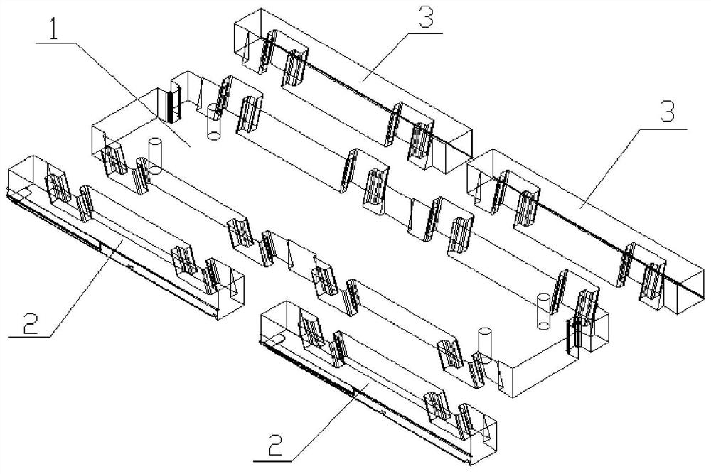
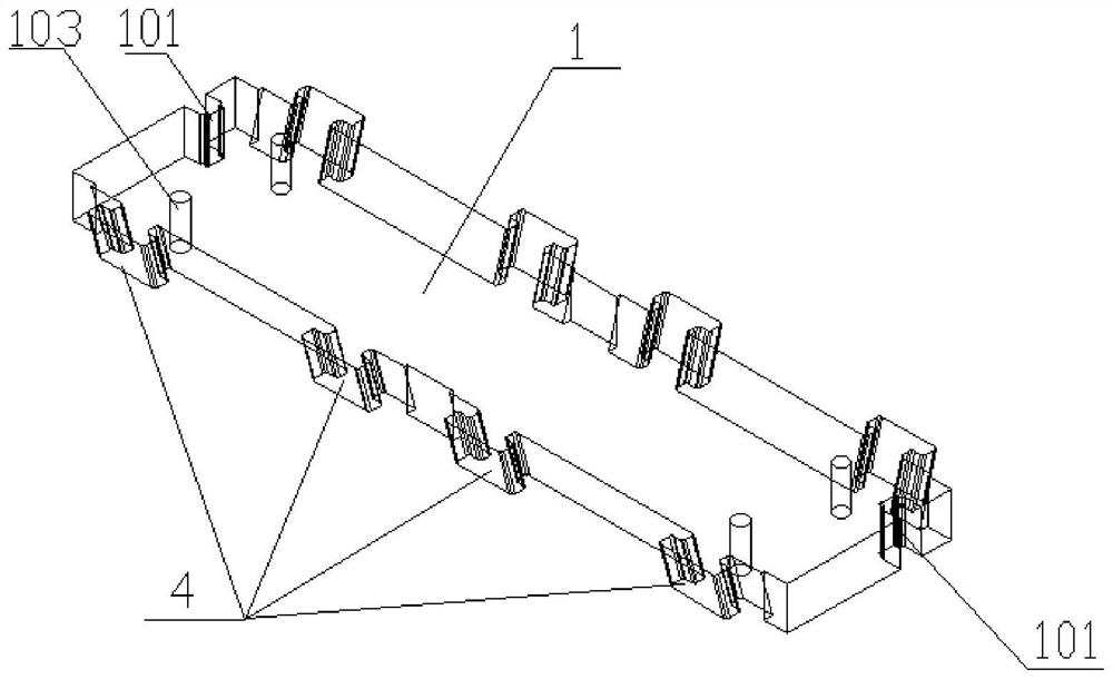
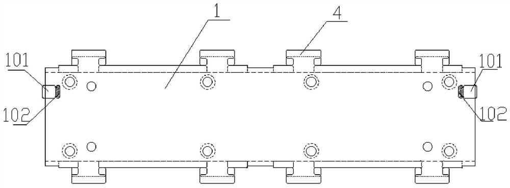
[0044] This embodiment provides a separate bending upper formwork assembly, including an upper formwork 1 , and the separate bending upper formwork assembly further includes a first bending connecting piece 2 and a second bending connecting piece 3 . The side is provided with a convex block 4, the protrusion end of the protrusion block 4 is connected to the upper template 1, and the first bending connector 2 and the second bending connector 3 are provided with fixed grooves that match the protrusion block 4. 5. The protruding block 4 is fitted with the fixing groove 5, so that the first bending connector 2 and the second bending connector 3 are respectively installed on both sides of the upper template 1;

[0045] A first bending angle 201 is formed on the side of the first bending connector 2 away from the fixing groove 5 , and a second bending angle 301 is formed on the side of the second bending connecting member 3 on the fixing groove 5 .

[0046] As a preferred embodiment...


PUM


Abstract

The invention relates to a separated bending upper die plate assembly which comprises an upper die plate, the separated bending upper die plate assembly further comprises a first bending connecting piece and a second bending connecting piece, convex protruding blocks are arranged on the two opposite sides of the upper die plate, the end, with the smaller diameter, of each protruding block is connected with the upper die plate, and the other end, with the smaller diameter, of each protruding block is connected with the first bending connecting piece. The first bending connecting piece and the second bending connecting piece are both provided with fixing grooves matched with the protruding blocks, the side, away from the fixing grooves, of the first bending connecting piece is provided with a first bending angle, and the side, away from the fixing grooves, of the second bending connecting piece is provided with a second bending angle. Compared with the prior art, the invention has the advantages of reliable positioning and connection, convenience in replacement, wide application range and the like.

Description

technical field [0001] The invention relates to the field of bending molds, in particular to a separate bending upper template assembly. Background technique [0002] In the field of machinery manufacturing, for the manufacture of plate-shaped parts of various products, mass production is generally achieved through molds. The types of molds are divided into bending molds, integral molding molds, trimming molds, etc., of which bending is the most commonly used. mold. [0003] The invention with the publication number of CN108296352A discloses a production system for the cover plate of a range hood, and aims to provide a system capable of conveniently punching the cover plate of the range hood. Bending and forming operations to increase the overall production efficiency of the lamp cover production system, the main point of the technical solution is that it includes punching dies, bending dies, forming dies and blanking dies which are arranged in sequence, and the bending die...

Claims


Application Information

Patent Timeline
Patent Type & Authority Applications(China)
IPC IPC(8): B21D5/02B21D37/12
CPCB21D5/0209B21D5/0254B21D37/12
Inventor 聂玉贵
Owner SHANGHAI QIANGJING METAL PROD
Why Eureka
Try Eureka