
Rigid frame-continuous steel-concrete hybrid beam railway bridge structure

A technology for railway bridges and hybrid beams, applied in bridges, bridge construction, bridge materials, etc., can solve problems such as the inability to meet the spanning capacity of large-span railway bridges, the applicability of uneven temperature settlement, the unfavorable piers, and the increased construction difficulty and construction period. , to achieve the effect of reducing the number of statically indeterminate times, wide economy and applicability, and shortening the construction period

Pending Publication Date: 2022-07-01
CHINA RAILWAY SIYUAN SURVEY & DESIGN GRP
View PDF9 Cites 0 Cited by
  • Summary
  • Abstract
  • Description
  • Claims
  • Application Information

AI Technical Summary

Problems solved by technology

[0003] In recent years, due to the high-speed development of my country's highways and railways, especially the rapid development of high-speed railways and rail transit projects, on the one hand, traditional rigid-frame bridges will suffer from mid-span deflection and web cracks during long-term operation. On the one hand, because the applicability of traditional continuous rigid frame bridges to temperature and uneven settlement is particularly unfavorable when the pier is relatively short, traditional concrete continuous rigid frame bridges are no longer able to meet the spanning capacity of long-span railway bridges.
Although continuous beam arches and low-tower cable-stayed bridges have appeared that strengthen the traditional concrete continuous beams to improve the spanning capacity, the construction difficulty and construction period have been correspondingly increased, and the project investment has also increased a lot. To transport girders, the bridge deck needs to be made wider, which is less economical. Although some people have proposed to replace the mid-span concrete of traditional continuous rigid frame bridges with lightweight concrete or steel box girder structures to improve the spanning capacity of the structure, However, the problem of poor applicability of rigid frame bridges has not been solved when the piers are too short, and when the concrete section is inconsistent with the steel box girder section, new challenges have been put forward for the structure of the steel-concrete joint section, and the traditional long-span rigid frame The problem of long-term deflection of the bridge also needs to be solved urgently

Method used


Image

  • Rigid frame-continuous steel-concrete hybrid beam railway bridge structure
  • Rigid frame-continuous steel-concrete hybrid beam railway bridge structure
  • Rigid frame-continuous steel-concrete hybrid beam railway bridge structure

Examples


Embodiment Construction

[0025] The technical solutions in the embodiments of the present invention will be clearly and completely described below with reference to the accompanying drawings in the embodiments of the present invention. Obviously, the described embodiments are only a part of the embodiments of the present invention, but not all of the embodiments. Based on the embodiments of the present invention, all other embodiments obtained by persons of ordinary skill in the art without creative efforts shall fall within the protection scope of the present invention.

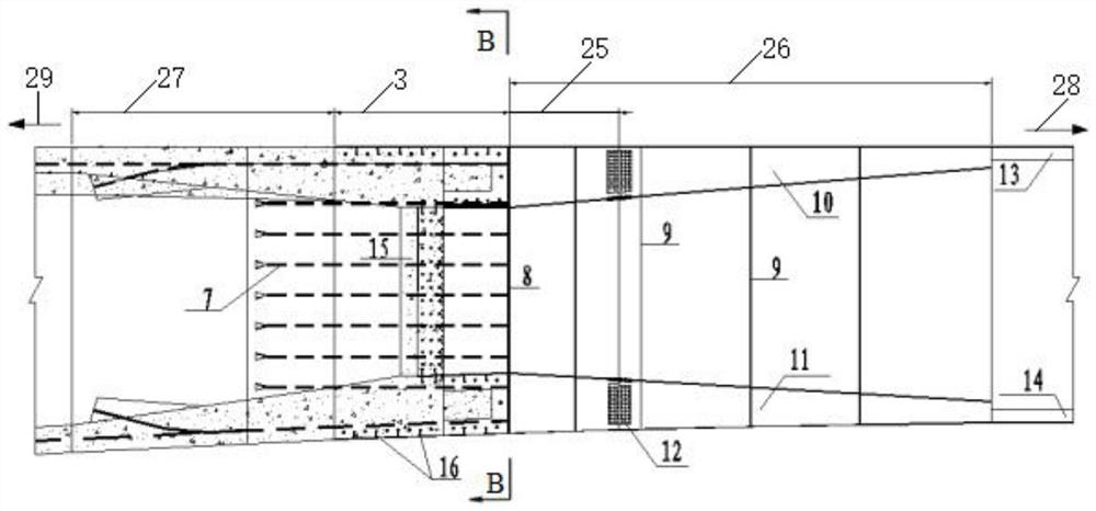
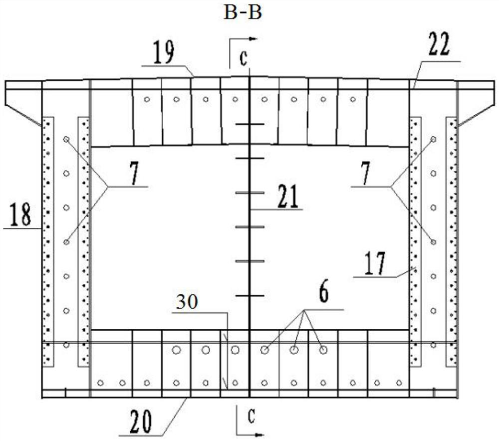
[0026] like Figure 1-Figure 4 , the embodiment of the present invention provides a rigid frame-continuous steel-concrete hybrid beam railway bridge structure connecting a single-box single-chamber concrete section and a single-box double-chamber steel box girder section, including a steel box girder 2 in the middle, a steel box girder in the middle The concrete beam sections 1 on both sides of the beam 2, the steel box girder 2 and...


PUM


Abstract

The invention provides a rigid frame-continuous steel-concrete mixed beam railway bridge structure which comprises a steel box beam located in the middle and concrete beam sections located on the two sides of the steel box beam, the steel box beam is connected with the concrete beam sections through steel-concrete combined sections, the concrete beam section on one side is supported by a rigid arm main pier, and the concrete beam section on the other side is supported by a rigid arm main pier. And the concrete beam section on the other side is supported by a common main pier. On the basis of a traditional concrete continuous rigid frame, a midspan local concrete beam section is replaced with the steel box beam, the beam height is reduced, the self weight is reduced, the spanning capacity is improved, the construction period is shortened, and the economical efficiency is improved. On the basis of a traditional concrete continuous rigid frame, a rigid arm pier is replaced with a traditional pier, the statically indeterminate frequency of the structure is reduced, the adaptability of the structure to loads such as temperature and differential settlement is improved, and the application range of the structure is wider.

Description

technical field [0001] The invention relates to the field of railway bridge engineering, in particular to a rigid frame-continuous steel-concrete hybrid girder railway bridge structure. Background technique [0002] Concrete continuous rigid-frame bridges are widely used in highway and railway bridge projects due to their high structural rigidity, mature construction technology, large spanning capacity, good driving comfort, good durability, and low cost. [0003] In recent years, due to the rapid development of my country's highway and railway industries, especially the rapid development of high-speed railways and rail transit projects, on the one hand, traditional rigid-frame bridges will suffer from diseases such as mid-span deflection and web cracks during long-term operation. On the one hand, the applicability of traditional continuous rigid-frame bridges to temperature and uneven settlement is particularly unfavorable when the piers are low, so traditional concrete cont...

Claims


Application Information

Patent Timeline
Patent Type & Authority Applications(China)
IPC IPC(8): E01D2/04E01D101/28
CPCE01D2/04E01D2101/285
Inventor 杨朝龙文望青严爱国王德志余泽宽宋子威占将德张朝霞聂利芳付小军陈晓辉武兵葛建刚陈锋
Owner CHINA RAILWAY SIYUAN SURVEY & DESIGN GRP
Learn More