
Switching device and heat dissipation control method thereof

A technology of switchgear and heat dissipation module, which is applied in the direction of cooling/ventilation, separation methods, chemical instruments and methods of substations/switchgears, etc., which can solve the problems of effective heat dissipation in difficult chambers, and achieve timely and effective heat dissipation

Pending Publication Date: 2022-07-01
NINGBO AUX HIGH TECH
View PDF1 Cites 0 Cited by
  • Summary
  • Abstract
  • Description
  • Claims
  • Application Information

AI Technical Summary

Problems solved by technology

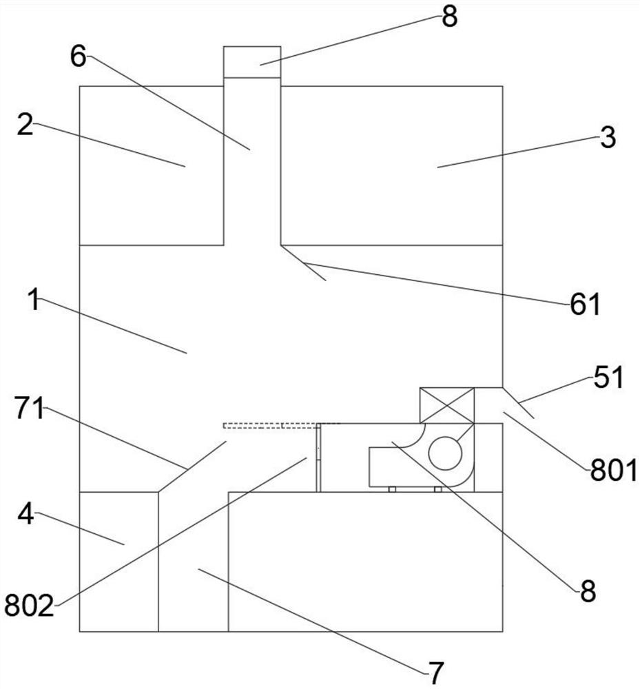
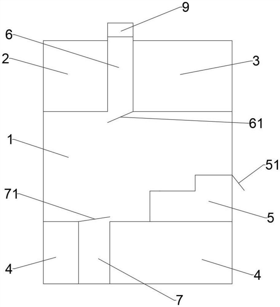
[0006] In view of this, the present invention aims to propose a switchgear and its heat dissipation control method to solve the problem in the prior art that it is often difficult to timely and effectively dissipate heat from each chamber in the central switchgear

Method used


Image

  • Switching device and heat dissipation control method thereof
  • Switching device and heat dissipation control method thereof
  • Switching device and heat dissipation control method thereof

Examples


Embodiment Construction

[0029] The inventive concepts of the present disclosure will be described below using terms commonly used by those skilled in the art to convey the substance of their work to others skilled in the art. These inventive concepts may, however, be embodied in many different forms and should not be considered limited to the embodiments described herein.

[0030] It should be noted that the embodiments of the present invention and the features of the embodiments may be combined with each other under the condition of no conflict.

[0031] The present invention will be described in detail below with reference to the accompanying drawings and in conjunction with the embodiments.

[0032] In the existing mid-mounted switchgear, it is usually divided into upper, middle and lower three-layer structure. The upper layer is the busbar room and the instrument room (isolated from each other), the middle layer is the circuit breaker room, and the lower layer is the cable room. In the actual op...


PUM


Abstract

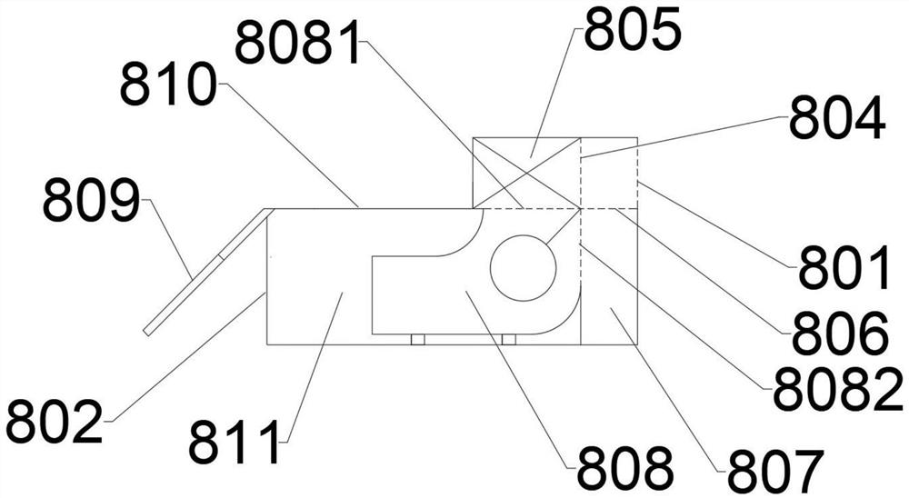
The invention provides a switch device and a heat dissipation control method thereof.The switch device comprises a circuit breaker chamber, a bus chamber, an instrument chamber, a cable chamber and a heat dissipation module, an assembly chamber is arranged in the circuit breaker chamber, the heat dissipation module is detachably connected with the assembly chamber, a main air inlet of the heat dissipation module is communicated with the environment, and an auxiliary air inlet of the heat dissipation module is communicated with the bus chamber. A main air outlet of the heat dissipation module is communicated with the circuit breaker chamber; a pressure relief channel is formed between the bus chamber and the instrument chamber, an inlet end of the pressure relief channel is communicated with the circuit breaker chamber, an outlet end of the pressure relief channel is provided with a pressure relief device, a heat exchange channel is arranged in the cable chamber, the heat exchange channel is separated from an inner cavity of the cable chamber, and the heat exchange channel is communicated with the circuit breaker chamber; according to the invention, through the arrangement of the heat dissipation module, the pressure relief channel and the heat exchange channel in the switch device, ventilation and heat dissipation can be carried out on each chamber, so that heat dissipation can be carried out on each chamber in the switch device timely and effectively.

Description

technical field [0001] The invention relates to a switchgear and a heat dissipation control method thereof, in particular to a mid-mounted switch cabinet and a heat dissipation control method thereof. Background technique [0002] For switchgears such as mid-mounted switchgear, they are often used for control, protection, monitoring and measurement of power circuits, such as power plants, power transmission of small and medium generators, and secondary substations of power systems. Electricity, power transmission, distribution of industrial and mining enterprises and institutions, and starting of large high-voltage motors, etc. [0003] For the conventional mid-mounted switchgear structure, it is often divided into an upper, middle and lower three-layer structure. The upper layer is the busbar room and the instrument room (isolated from each other), the middle layer is the circuit breaker room, and the lower layer is the cable room. In the actual operation of the central sw...

Claims


Application Information

Patent Timeline
Patent Type & Authority Applications(China)
IPC IPC(8): H02B1/56H02B1/30H02B1/28B01D53/28
CPCH02B1/565H02B1/30H02B1/28B01D53/28B01D2257/80B01D2251/608
Inventor 郭海平芮绍伟孟海军呼延海平唐健
Owner NINGBO AUX HIGH TECH
Learn More