Cell separation equipment and application of cell separation equipment to treatment of leukemia by utilizing vertical reduction, progressive increase and acceleration
A technology for separating equipment and cells, which is applied in the field of cell separation to achieve the effect of facilitating extraction and improving removal efficiency
- Summary
- Abstract
- Description
- Claims
- Application Information
AI Technical Summary
Problems solved by technology
Method used
Image
Examples
Embodiment 1
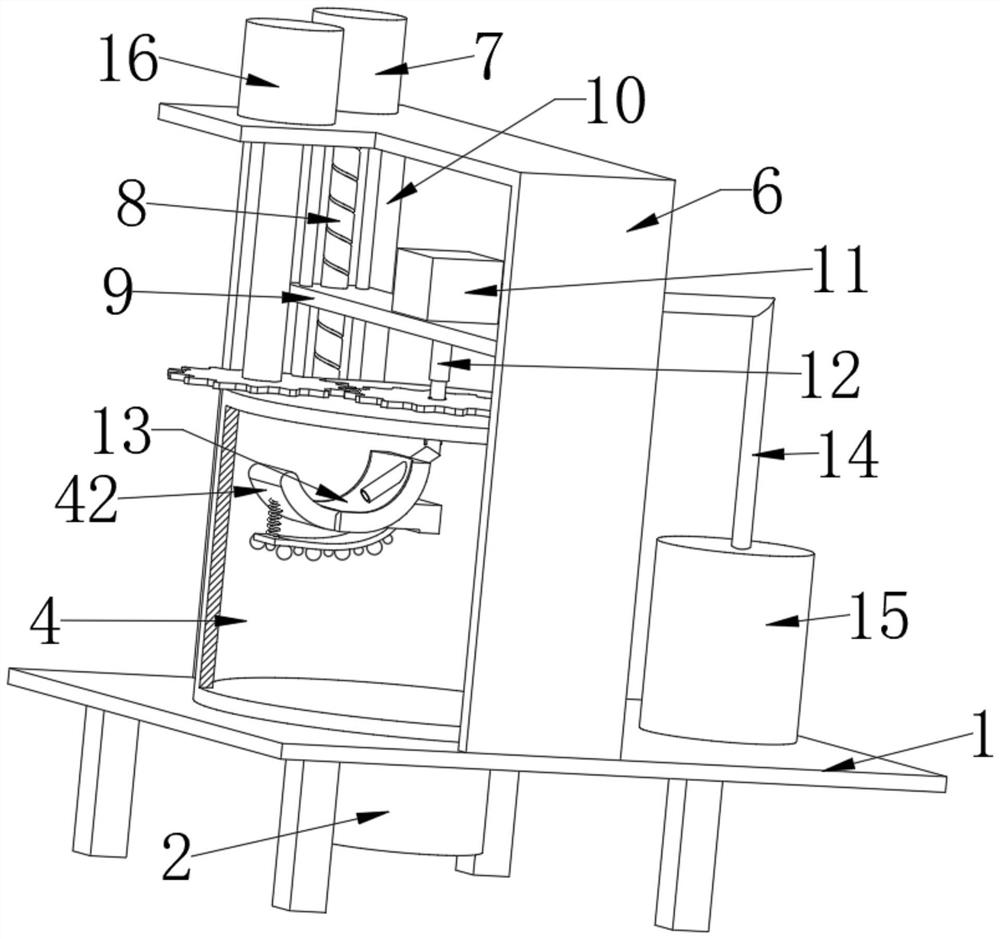
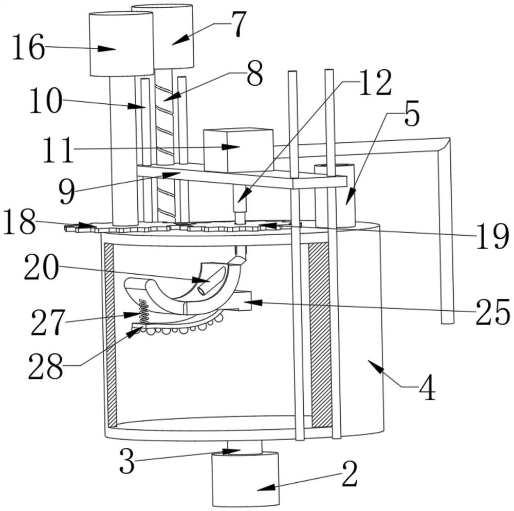
[0031] see Figure 1-2, a cell separation device, comprising a first support frame 1, a first motor 2 is installed at the bottom of the first support frame 1, and the output end of the first motor 2 is connected with a liquid mixing bucket 4 through a first shaft 3, which is located at a convenient location for observation and separation. In some cases, the mixing bucket 4 is made of transparent material, the first rotating shaft 3 penetrates the first support frame 1, the first rotating shaft 3 is rotatably connected with the first support frame 1, the surface of the mixing bucket 4 is fixedly connected with a feeding pipe 5, and the first The surface of the support frame 1 is fixedly connected with a second support frame 6, the surface of the second support frame 6 is mounted with a second motor 7, and the output end of the second motor 7 is fixedly connected with a screw rod 8, and the screw rod 8 is connected to the second support frame. 6. Rotationally connected, the oute...
Embodiment 2
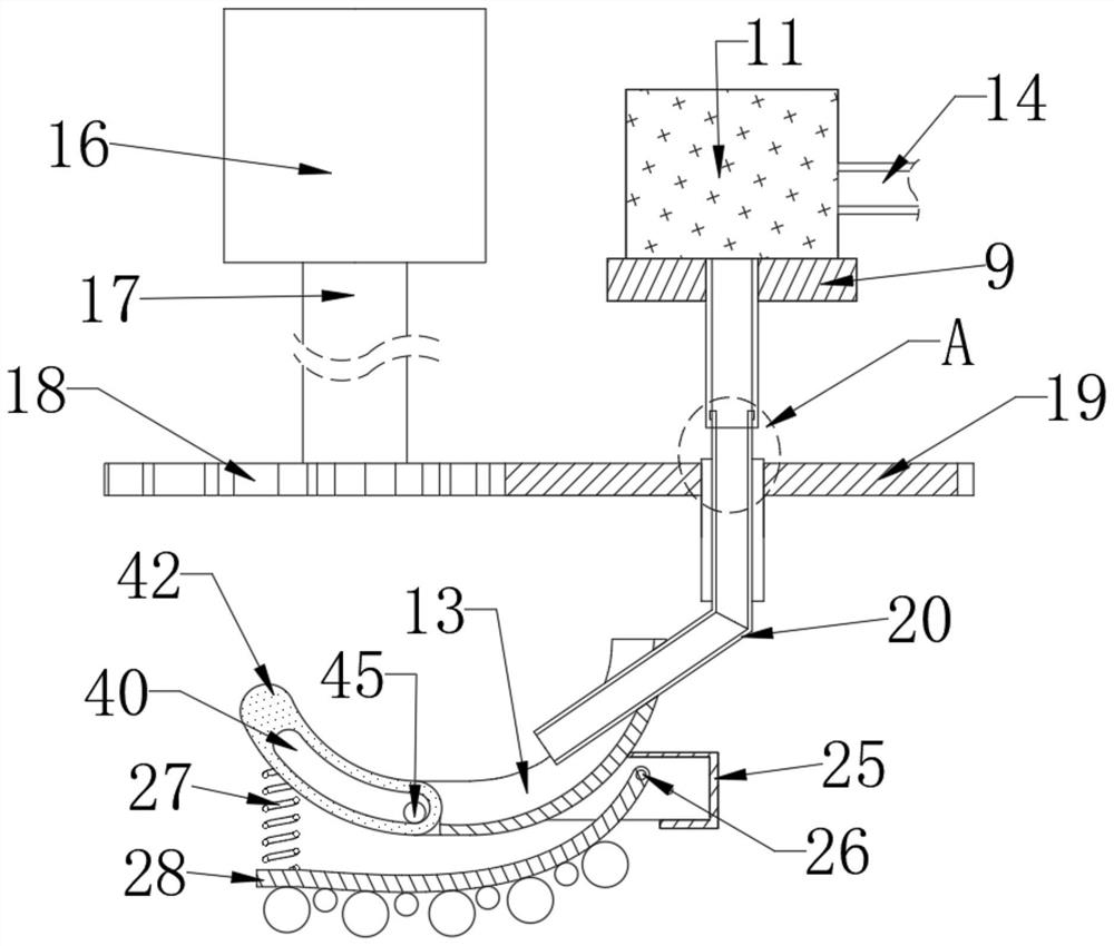
[0034] This embodiment is an improvement made on the basis of Embodiment 1. On the basis of the accompanying drawings of Embodiment 1, please combine the attached drawings again. Figure 3-4 .
[0035] A third motor 16 is mounted on the surface of the second support frame 6 , the output end of the third motor 16 is connected with a first gear 18 through the second rotating shaft 17 , the side wall of the first gear 18 is engaged with a second gear 19 , and the second gear 19 is engaged with the second gear 19 . The inner wall of the gear 19 is coaxially provided with a second liquid inlet pipe 20, one end of the second liquid inlet pipe 20 is rotatably connected with the first liquid inlet pipe 12, and the other end of the second liquid inlet pipe 20 is fixedly connected with the scraper 13. The outer wall of the second liquid inlet pipe 20 is symmetrically and fixedly connected with sliding bars 22 , and the inner wall of the second gear 19 is symmetrically opened with first ...
Embodiment 3
[0039] This embodiment is an improvement made on the basis of Embodiment 2. On the basis of the attached drawings of Embodiment 2, please combine the attached drawings again. Figure 5-6 .
[0040] The side wall of the spatula 13 is fixedly connected with a third support frame 25 , the inner wall of the third support frame 25 is rotatably connected with a first rotating rod 26 , and the outer wall of the first rotating rod 26 is fixedly connected with a first movable plate 28 . A first spring 27 is arranged between the plate 28 and the spatula 13 , and a limit bar 29 is arranged on the inner wall of the third support frame 25 , and the limit bar 29 is used to limit the rotation angle of the first movable plate 28 .
[0041] The outer wall of the first rotating rod 26 is fixedly connected with the third gear 30, the side wall of the third gear 30 is meshed and connected with the fourth gear 31, and the fourth gear 31 is rotatably connected with the third supporting frame 25 thr...
PUM
 Abstract
Description
Claims
Application Information
 - R&D Engineer
- R&D Manager
- IP Professional
- Industry Leading Data Capabilities
- Powerful AI technology
- Patent DNA Extraction
Browse by: Latest US Patents, China's latest patents, Technical Efficacy Thesaurus, Application Domain, Technology Topic, Popular Technical Reports.
© 2024 PatSnap. All rights reserved.Legal|Privacy policy|Modern Slavery Act Transparency Statement|Sitemap|About US| Contact US: help@patsnap.com


