Compression resistance testing device for building materials

A technology for building materials and testing devices, which is used in measuring devices, analyzing materials, and testing the strength of materials by applying stable tension/pressure. It can solve problems such as operator injury, lack of protective function, etc. Bit, easy to operate effect

Pending Publication Date: 2022-07-05
江西固特尤新材料有限公司
View PDF1 Cites 0 Cited by
  • Summary
  • Abstract
  • Description
  • Claims
  • Application Information

AI Technical Summary

Problems solved by technology

[0005] The purpose of the present invention is to provide a building material compression test device, which has the advantages of protection function and avoiding operator injury, and solves the problem of not having protection function and easily causing operator injury

Method used


Image

  • Compression resistance testing device for building materials
  • Compression resistance testing device for building materials
  • Compression resistance testing device for building materials

Examples


Embodiment 1

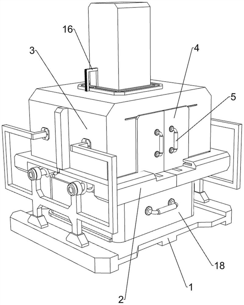
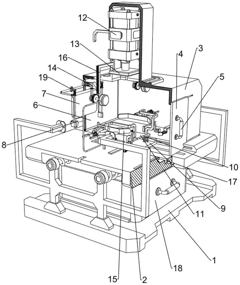
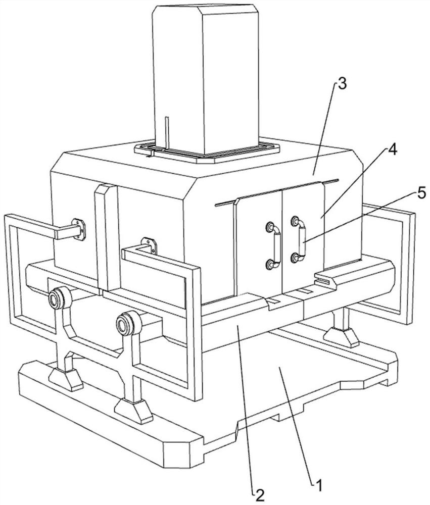
[0038] A compressive test device for building materials, refer to figure 1 , figure 2 , image 3 , Figure 4 , Figure 5 , Image 6 , Figure 7 , Figure 8 , Figure 10 , Figure 12 , Figure 13 and Figure 14 , including a support frame 1, a sliding plate 2, a protective frame 3, a baffle 4, a first handle 5, a rotating plate 6, a transparent plate 7, a second handle 8, a first sliding member 9, and a first lifting plate 10 , shock-absorbing spring 11, hydraulic cylinder 12, second lifting plate 13, detection mechanism 14 and clamping mechanism 15, the left and right sides of the middle of the support frame 1 are slidably connected with the sliding plate 2, and the upper and inner sides of the support frame 1 are connected There is a protective frame 3. The protective frame 3 can prevent debris of building materials from splashing around. The front side of the protective frame 3 is slidably connected with two baffles 4. The two baffles 4 are respectively slidingly ...

Embodiment 2

[0043] On the basis of Example 1, refer to figure 1 , figure 2 , Figure 10 and Figure 11, also includes a pulling mechanism 16, the pulling mechanism 16 includes a rack 160, a connecting piece 161, a one-way gear 162, a pulley 163, a pulling rope 164, a first return spring 165, a scroll spring 166 and a rotating shaft 167, the second A rack 160 is symmetrically connected to the rear side of the top of the lift plate 13 , and a connecting piece 161 is symmetrically connected to the top of the protective frame 3 . Both are connected with one-way gears 162. When the rack 160 moves downward, the one-way gears 162 will not rotate. The front sides of the two rotating shafts 167 are connected with pulleys 163, and the two pulleys 163 are both connected with pulleys. 164. The pull rope 164 is used to pull the sliding plate 2 to the outside. The two pull ropes 164 slide through the left and right sides of the protective frame 3 respectively, and the other ends of the two pull rop...

Embodiment 3

[0046] On the basis of Example 2, refer to figure 1 , figure 2 and Figure 12 , also includes a push mechanism 17, the push mechanism 17 includes a motor 170, a screw 171 and a mounting block 172, the inner rear side of the two sliding plates 2 are equipped with a motor 170, and the output shafts of the two motors 170 are connected with the screw 171, Mounting blocks 172 are welded to the outside of the two screws 171 by means of threads. The mounting blocks 172 are used to move the first sliding member 9 back and forth. The two mounting blocks 172 are respectively connected to the two first sliding members 9 by welding.

[0047] When the building materials need to be placed, the two motors 170 can be activated. The output shafts of the two motors 170 drive the two screws 171 to rotate, and the two screws 171 drive the two mounting blocks 172 and the first sliding member 9 to move forward. , when the two first sliders 9 move to the front side to the proper position, the two...


PUM


Abstract

The invention relates to a testing device, in particular to a building material compression resistance testing device. The invention provides a building material compression resistance testing device which has a protection function and can prevent operators from being injured. A building material compression resistance testing device comprises a supporting frame, sliding plates, a protection frame, baffles, a first grip, a rotating plate and the like, the sliding plates are slidably connected to the left side and the right side of the middle of the supporting frame, the protection frame is connected between the inner sides of the upper portion of the supporting frame, and the two baffles are slidably connected to the front side of the protection frame; the two baffles are in sliding fit with the two sliding plates correspondingly, the front sides of the two baffles are both connected with first grips, and the upper side of the rear portion of the protection frame is rotationally connected with a rotating plate. By arranging the protection frame, the protection frame can prevent building material chippings from splashing all around, the situation that the building material chippings are splashed to the body of an operator is avoided, and the operator cannot be injured.

Description

technical field [0001] The invention relates to a testing device, in particular to a compression testing device for building materials. Background technique [0002] Building materials refer to the materials used in the construction of buildings and structures, and are the material basis of construction projects. In order to ensure the quality of building materials, it is necessary to carry out compression tests on building materials during the production process of building materials. [0003] At present, a building material pressure detection device with publication number CN209069736U and application number CN201821805387.8 has been published, which belongs to the technical field of building material detection equipment, including base, frame, screw seat, hand screw, display, pressure plate, pressure detection Tray, ash collecting tray and pressure detector, the upper end of the base is provided with a frame, the upper end of the frame is provided with a screw seat, the ...

Claims


Application Information

Patent Timeline
IPC IPC(8): G01N3/08G01N3/04G01N3/02
CPCG01N3/08G01N3/04G01N3/02
Inventor 郭黎男
Owner 江西固特尤新材料有限公司
Why Eureka
Try Eureka