Energy-saving underwater communication equipment
A communication equipment, energy-saving technology, applied in the direction of cable laying equipment, cable installation, electrical components, etc., can solve the problems of cable protective layer rupture and damage, being bitten by creatures, friction, etc., to improve stable operation and improve stability sexual effect
- Summary
- Abstract
- Description
- Claims
- Application Information
AI Technical Summary
Problems solved by technology
Method used
Image

Examples
Embodiment 1
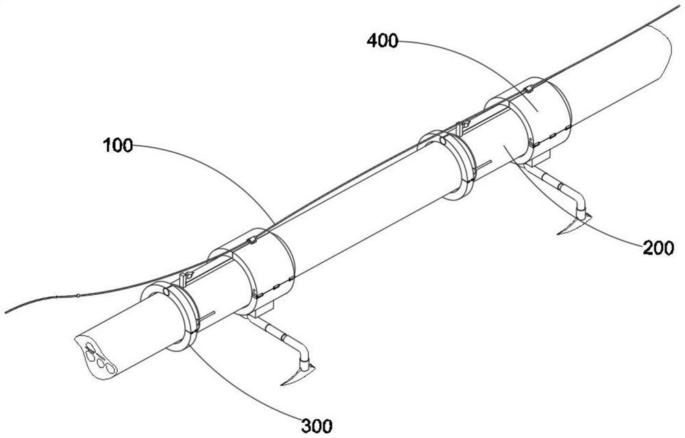
[0034] combine figure 1 and figure 2 as well as Figure 4 to Figure 7 As shown, an energy-saving underwater communication device provided by the present invention includes a traction mechanism 100, a cable tightening mechanism 200, a stabilization mechanism 300 and a cable strengthening mechanism 400, wherein the cable tightening mechanism 200 is installed on the traction mechanism 100. In addition, the stabilization mechanism 300 is connected to the cable tightening mechanism 200 , and further, the cable strengthening mechanism 400 is installed on the cable tightening mechanism 200 .
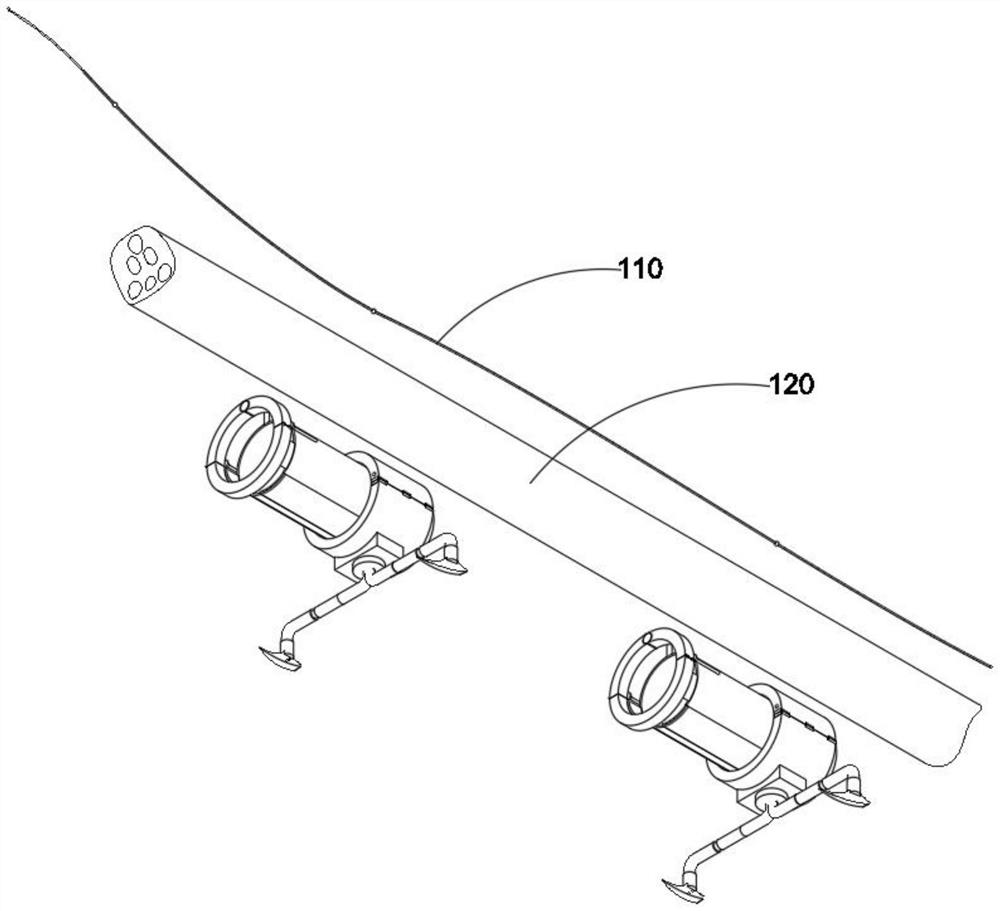
[0035] The traction mechanism 100 includes a tether 110 and an underwater cable 120, the cable tightening mechanism 200 includes a positioning member 210, a cutting head 220, a primary surrounding member 230, a secondary surrounding member 240, a protective spacer 250 and a fastener 260, the stabilization mechanism 300 includes a base 310, an arc plate 320, a first clamp arm 330, a spring bu...
Embodiment 2
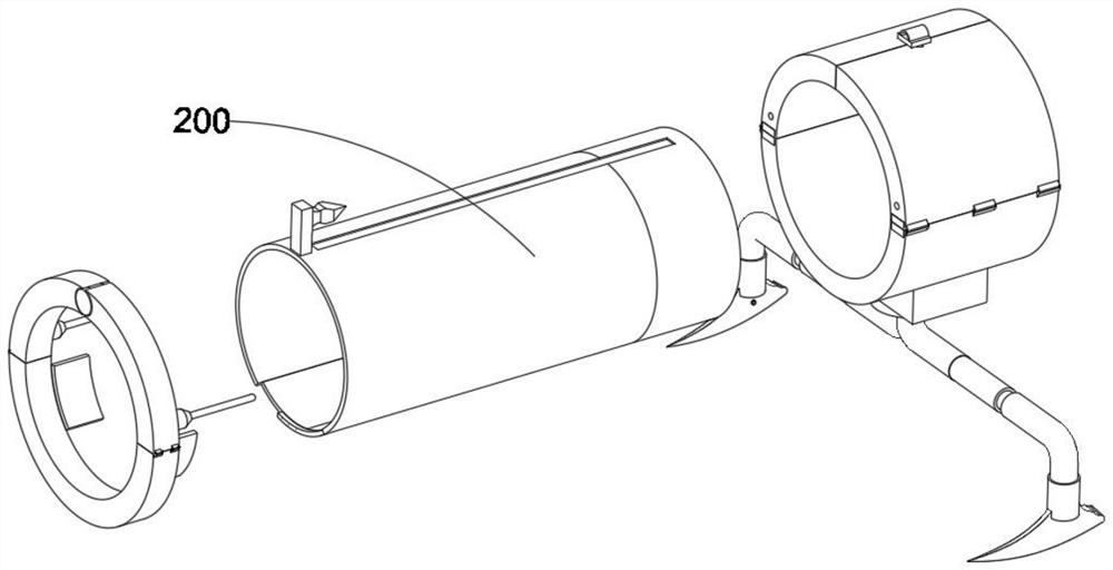
[0038] combine image 3 as well as Figure 5 to Figure 7 As shown, on the basis of Embodiment 1, the positioning member 210 is made of thickened stainless steel arc plate, and the thickened stainless steel arc plate is sprayed with waterproof paint, and the top of the positioning member 210 is provided with a horizontal T-shaped chute At the same time, the two ends of the main surrounding member 230 are provided with symmetrically distributed holes, the fastener 260 is composed of a main rod, a spring and a sub-rod, and the inner end of the female rod in the fastener 260 is adapted to be installed on the main surrounding member 230 holes at both ends.
[0039] By using the chute on the top of the L-shaped sliders on the inside of the two wing slides 420, when the connecting end of the lead rope 440 and the pad 450 moves to the position of the inner blade of the cutting head 220, the lead rope 440 and the The cushion member 450 will be quickly separated, and when the guide ro...
Embodiment 3
[0041] combine Figure 4 As shown, on the basis of the first embodiment, the outer end of the second clamping arm 350 is provided with two circular pads, and the outer end of the first clamping arm 330 is provided with circular protrusions, and the circular protrusions fit together Penetrates into two circular pads.
[0042] Two symmetrically distributed positioning members 360 are installed on one side of the second clamping arm 350 and the first clamping arm 330 close to the positioning member 210, and the hooks at the outer ends of the positioning members 360 are adapted to penetrate to the inner side of the two lateral wing slide plates 420, thereby The first clamping arm 330 and the second clamping arm 350 can tightly fix and tighten the two side wing slide plates 420 .
PUM
 Abstract
Description
Claims
Application Information
 - R&D Engineer
- R&D Manager
- IP Professional
- Industry Leading Data Capabilities
- Powerful AI technology
- Patent DNA Extraction
Browse by: Latest US Patents, China's latest patents, Technical Efficacy Thesaurus, Application Domain, Technology Topic.
© 2024 PatSnap. All rights reserved.Legal|Privacy policy|Modern Slavery Act Transparency Statement|Sitemap