Tool magazine speed reducer

A technology of reducer and tool magazine, which is applied in metal processing machinery parts, manufacturing tools, metal processing, etc., can solve the problems of reduced precision, reduced product yield, and high difficulty, so as to reduce the difficulty of disassembly and assembly, reduce the difficulty of replacement, and reduce the The effect of precision loss

Active Publication Date: 2022-07-08
冈田精机(常州)有限公司
View PDF8 Cites 0 Cited by
  • Summary
  • Abstract
  • Description
  • Claims
  • Application Information

AI Technical Summary

Problems solved by technology

[0003] The structural principle of the original worm gear reducer leads to the inevitable wear between the turbine and the worm due to friction. The wear between the turbine teeth and the worm teeth will cause the turbine teeth to collide with the worm teeth, causing abnormal noise. It will le

Method used


Image

  • Tool magazine speed reducer
  • Tool magazine speed reducer
  • Tool magazine speed reducer

Examples


Example Embodiment

[0046] The present invention will now be described in further detail with reference to the accompanying drawings. These drawings are all simplified schematic diagrams, and only illustrate the basic structure of the present invention in a schematic manner, so they only show the structures related to the present invention. The present invention is described in detail by using structural schematic diagrams, etc. The schematic diagrams are only examples, which should not limit the protection scope of the present invention. In addition, the three-dimensional space of length, width and depth should be included in the actual production.

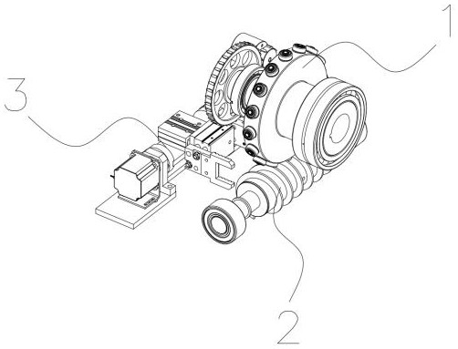
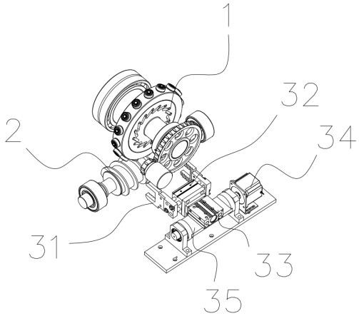
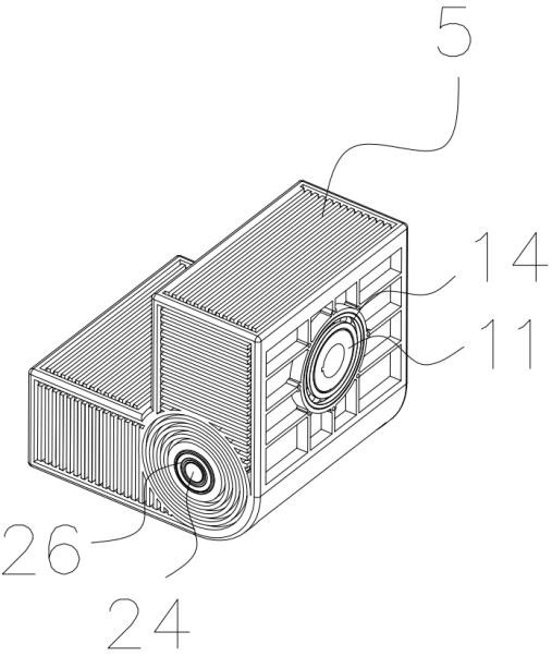
[0047] see Figure 1-Figure 14 , a tool magazine reducer, including an input rod assembly 2, an input rod quick-release coupling device 4, an output wheel assembly 1, an automatic disassembly device 3 and a casing 5, the output wheel assembly 1 can be rotatably fixed On the casing 5, the output wheel assembly 1 includes an output wheel 11 and a pl...


PUM


Abstract

The invention relates to the technical field of machine tool equipment, in particular to a tool magazine speed reducer which comprises an input rod, an input rod quick-release connecting shaft device, an output wheel, an automatic dismounting device and a box shell, the output wheel is rotatably fixed to the box shell, a plurality of roller assemblies are rotatably connected to the circumference of the output wheel, the roller assemblies are arranged at equal angles, and the automatic dismounting device is arranged on the box shell. The problem that the worm wheel and the worm are damaged due to friction and are not easy to replace is solved, sliding friction is changed into rolling friction through the roller assemblies, and the problem that the precision is reduced due to abrasion between the worm wheel and the worm is greatly solved.

Description

technical field [0001] The invention relates to the technical field of machine tool equipment, in particular to a tool magazine reducer. Background technique [0002] The transmission mechanism of the disc tool magazine of the machining center generally uses more than 20 tools. These tools are installed in the tool pocket of the chain. When many different tools are used, the tool magazine needs to be rotated and positioned accurately and quickly. Servo drive. The existing servo transmission structure includes a worm gear reducer, a servo motor, a mechanism body, a driving gear, a bearing, a nut, a rotating shaft, a spacer, a driven gear, an upper mounting frame and a lower mounting frame. Among them, the worm gear reducer is fixed on the mechanism body through the upper bracket and the lower bracket, the servo motor is installed on the turbine worm reducer, and the rotating shaft is fixed on the mechanism body. When it needs to be rotated, the servo motor rotates, and the ...

Claims


Application Information

Patent Timeline
IPC IPC(8): B23Q3/157B23Q5/00
CPCB23Q3/157B23Q5/00Y02P70/10
Inventor 陈亮刘涛侯超李光中
Owner 冈田精机(常州)有限公司
Why Eureka
Try Eureka