Elevation installation method for H-shaped steel type column or support

An installation method and H-beam technology, applied in the processing of building materials, construction, building structure, etc., can solve the problems of inaccurate installation, and achieve the effect of speeding up the installation progress, high efficiency and slow progress.

Pending Publication Date: 2022-07-08
MCC5 GROUP CORP SHANGHAI
View PDF1 Cites 0 Cited by
  • Summary
  • Abstract
  • Description
  • Claims
  • Application Information

AI Technical Summary

Problems solved by technology

However, the utility model has no elevation when installing the H-shaped steel column, which will lead to the problem of inaccurate installation
[0004] To sum up, the prior art still lacks a fast and efficient method for the elevation installation of H-shaped steel columns or brackets.

Method used


Image

  • Elevation installation method for H-shaped steel type column or support
  • Elevation installation method for H-shaped steel type column or support
  • Elevation installation method for H-shaped steel type column or support

Examples


Embodiment 1

[0042] An elevation installation method for an H-shaped steel column or bracket of the present embodiment includes the following steps:

[0043] S1. Measure the depth of the cup mouth to ensure that the depth of the cup mouth meets the requirements of the grouting layer;

[0044] S2. Measure the elevation of the upper plane of the base of the cup mouth, and process the upper plane of the cup mouth to ensure that the upper plane of the cup mouth is flat;

[0045] S3. According to the weight of the H-shaped steel column or bracket and the width of the cup mouth, select the appropriate elevation plate;

[0046] S4. According to the depth of the H-shaped steel column or bracket inserted into the cup mouth, mark the insertion line on the H-shaped steel column or bracket that is flush with the elevation of the upper plane of the cup mouth foundation;

[0047] S5. Weld the elevation plate on the H-shaped steel column or bracket;

[0048] S6. Install H-shaped steel columns or bracke...

Embodiment 2

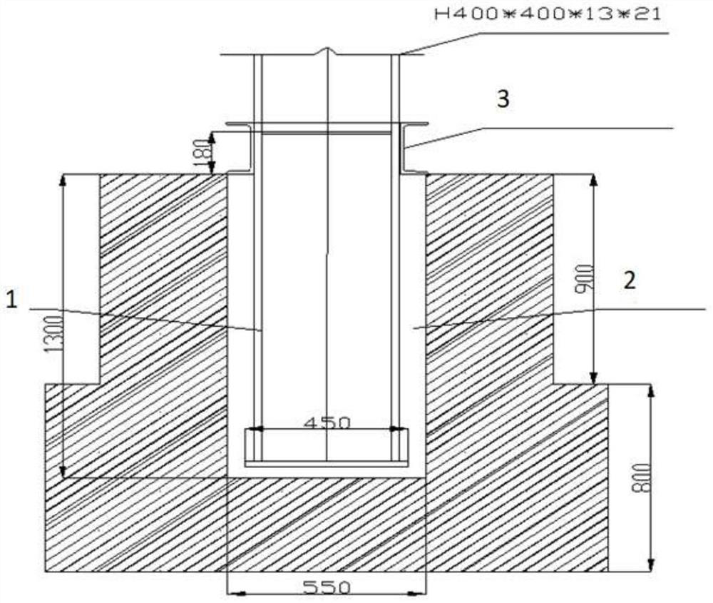
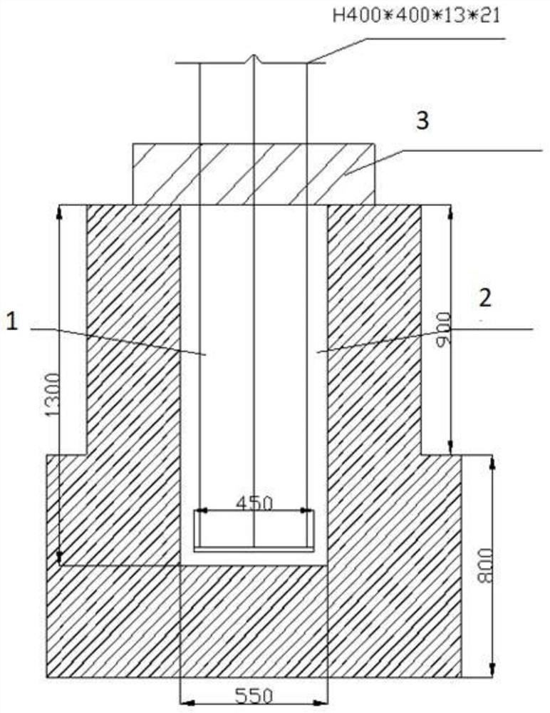
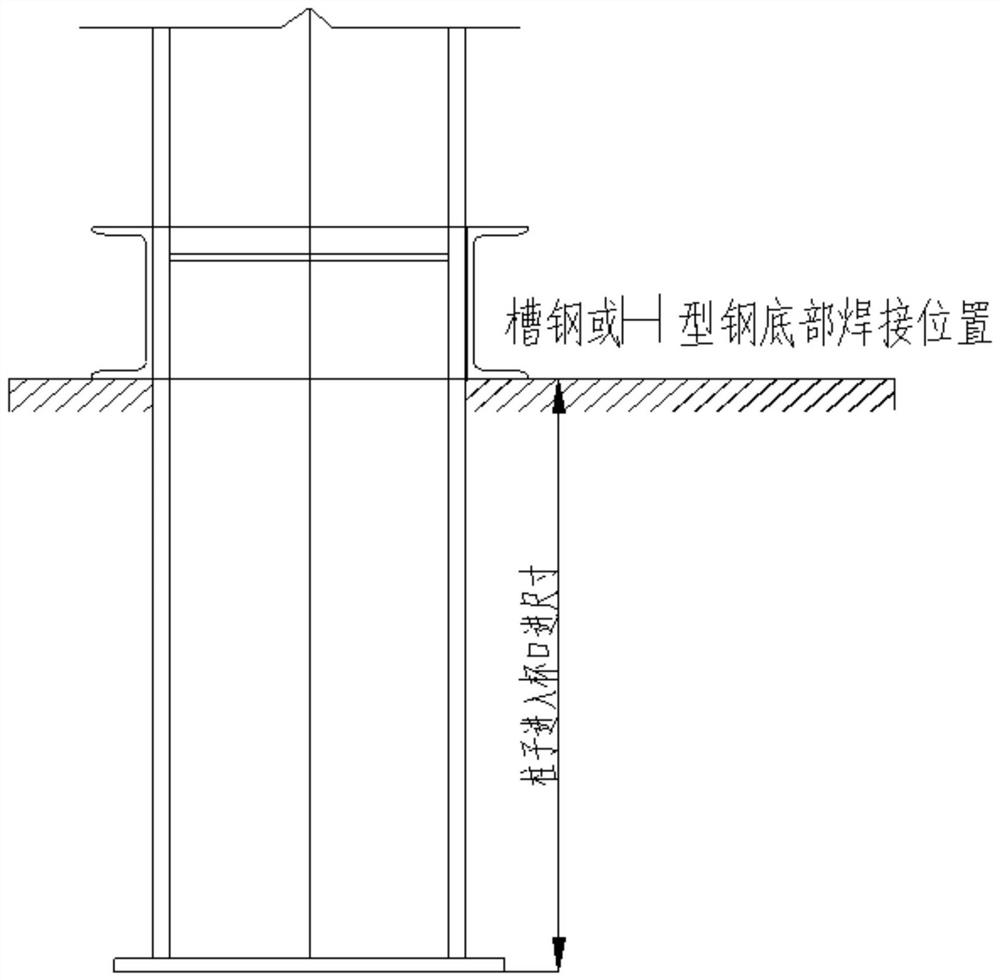
[0057] like Figure 1-4 As shown, an installation effect diagram of an elevation installation method of an H-shaped steel column or bracket is shown, including an H-shaped steel column or bracket 1 , a cup mouth 2 , an elevation plate 3 , and a triangular wedge 4 . like figure 1 and 2 As shown, part of the H-shaped steel column or bracket 1 is placed in the cup mouth 2, the H-shaped steel column or bracket 1 is welded with the benchmark plate 3, and the elevation plate 3 is supported on the cup mouth 2, so that the H-shaped steel column or bracket 1 extends The length of the cup inlet 2 is a design requirement. like image 3 As shown, the welding position of the H-shaped steel column or bracket 1 and the bottom of the elevation plate 3 is the plane elevation of the cup mouth 2, so as to ensure that the length of the H-shaped steel column or bracket 1 extending into the cup mouth 2 is more accurate. like Figure 4 As shown, the H-shaped steel column or bracket 1 is fixed ...


PUM


Abstract

The invention discloses an elevation mounting method for an H-shaped steel column or support, which comprises the following steps: S1, measuring the depth of a cup opening, and ensuring that the depth of the cup opening meets the requirements of a grouting layer; s2, the elevation of the upper plane of the cup rim foundation is measured, the upper plane of the cup rim is treated, and it is guaranteed that the upper plane of the cup rim is flat; s3, selecting an adaptive elevation plate according to the weight of the H-shaped steel column or the bracket and the width of a cup opening; s4, according to the depth of the H-shaped steel type column or the support inserted into the cup opening, an insertion line flush with the elevation of the upper plane of the cup opening foundation is marked on the H-shaped steel type column or the support; s5, the elevation plate is welded to the H-shaped steel type column or the support; s6, H-shaped steel type columns or supports are installed, and cable ropes are arranged in a pulling mode; s7, grouting is conducted on the H-shaped steel type column or the support, and after the requirement is met, the cable rope is dismantled for next-step installation; according to the elevation installation method for the H-shaped steel type column or support, elevation installation can be rapidly and efficiently carried out.

Description

technical field [0001] The invention relates to the technical field of building construction, in particular to an elevation installation method of an H-shaped steel column or bracket. Background technique [0002] The installation of H-beam columns or brackets is cup-type installation, especially in large-scale pipe gallery brackets or heavy-duty workshops. However, the size of the cup mouth is generally limited, and it is not easy for people to enter or enter to set the elevation. During the construction of the cup mouth, the general design requires a depth of about 50mm as the grouting layer, so the elevation control of H-shaped steel columns or brackets has become a difficult problem. [0003] A Chinese patent with publication number CN212984878U, a quick-assembled lightweight outdoor substation firewall, discloses a quick-assembled lightweight outdoor substation firewall. The utility model includes cup bases arranged at intervals, the reserved holes of each cup base are...

Claims


Application Information

Patent Timeline
Patent Type & Authority Applications(China)
IPC IPC(8): E04G21/14E04G21/18
CPCE04G21/14E04G21/18E04G21/1841
Inventor 陈军高良
Owner MCC5 GROUP CORP SHANGHAI
Why Eureka
Try Eureka