Self-unblocking sewage pump based on flexible pump body

A sewage pump and pump body technology, which is applied to the components of the pumping device for elastic fluid, the pump with flexible working elements, and the general water supply saving, etc. , Improve the effect of pumping efficiency

Pending Publication Date: 2022-07-08
TAIZHOU TAIFENG PUMP IND
0 Cites 0 Cited by

AI-Extracted Technical Summary

Problems solved by technology

[0005] Aiming at the deficiencies of the prior art, the present invention provides a self-clogging sewage pump based on a flex...

Method used

In traditional sewage pump, mostly adopt the impeller of high-speed rotation to carry out the pumping of sewage, but there are sundries in sewage, and sundries may be rubble, fiber etc., can cause damage to impeller, or block sewage pump, However, in this structure, the flexible membrane 17 and the arc rod 16 are pumped by means of pushing, which can eliminate the influence of sundries and ensure the normal pumping of sewage.
The convex edge that telescoping tube 1 lower end is provided with is fixedly connected with gasket 18, and gasket 18 is positioned between baffle plate 19 and ...

Abstract

The invention provides a self-unblocking sewage pump based on a flexible pump body, and relates to the field of water pumps. The self-unblocking type sewage pump based on the flexible pump body comprises a frame, the frame comprises connecting sections arranged on the left side and the right side, a flexible pipe is arranged on the inner side of the frame, a sliding frame is fixedly connected to the middle of the flexible pipe, the sliding frame is arranged in the length direction of angle steel in a sliding mode, and a flexible film is fixedly connected to the inner wall of the sliding frame. An arc-shaped rod is arranged on one side of the flexible film, one end of the arc-shaped rod is rotationally connected with the interior of the sliding frame, the other ends of the multiple arc-shaped rods are attached to one another, one connecting section is fixedly connected with an L-shaped water drawing pipe, and a telescopic pipe is connected with the interior of the other end of the water drawing pipe in a sleeved mode; a baffle is rotationally arranged in the lower end of the telescopic pipe. An impeller is omitted, a reciprocating pushing mechanism is adopted, liquid pumping is achieved, and the problem that a traditional pump is prone to being blocked and damaged is solved.

Application Domain

Technology Topic

Image

  • Self-unblocking sewage pump based on flexible pump body
  • Self-unblocking sewage pump based on flexible pump body
  • Self-unblocking sewage pump based on flexible pump body

Examples

  • Experimental program(1)

Example Embodiment

[0026] Example:
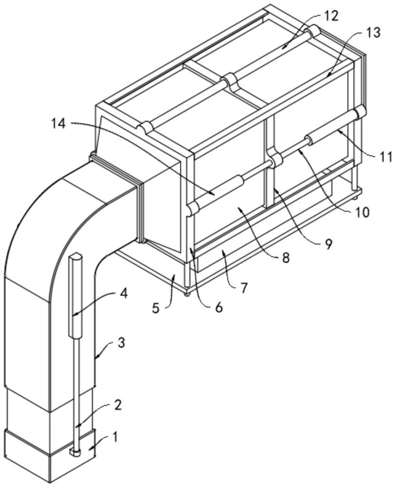
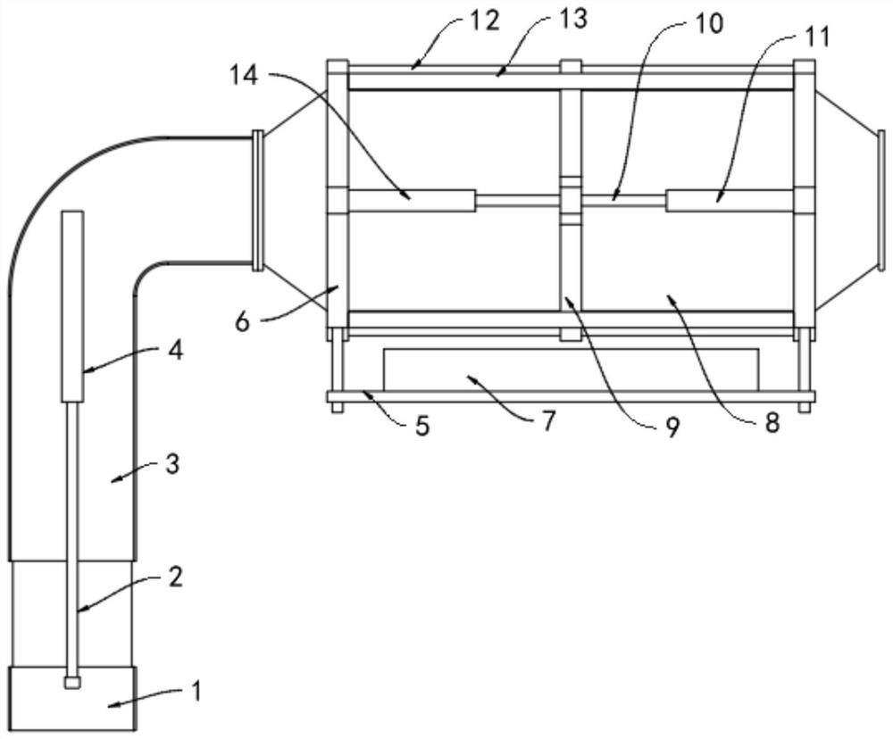
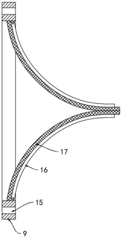
[0027] like Figure 1-4 As shown, the embodiment of the present invention provides a self-cleaning type sewage pump based on a flexible pump body, including a frame 6, the frame 6 is in the shape of a long direction, and is arranged symmetrically on the left and right, and the frame 6 includes connecting sections arranged on the left and right sides, The connecting section is used to connect the water inlet pipe and the water outlet pipe. Several angle steels 13 are fixedly connected between the two connecting sections, and the angle steels 13 are fixed at the corners of the connecting section to realize the fixed connection of the two connecting sections. The inner side of the frame 6 is provided There is a flexible tube 8, the flexible tube 8 is made of rubber or silicone, so that the flexible tube 8 can be bent, and its specific structure can also be similar to a bellows, to ensure that the flexible tube 8 can be stretched or compressed in the axial direction, and the flexible tube 8 The two ends are respectively fixedly connected with the two connecting sections, the middle part of the flexible pipe 8 is fixedly connected with a sliding frame 9, and the sliding frame 9 is slidably arranged along the length direction of the angle steel 13, that is, the sliding frame 9 divides the flexible pipe 8 into two left and right In part, when the sliding frame 9 slides back and forth, the flexible tube 8 on one side is stretched, and the flexible tube 8 on the other side is compressed.
[0028] A flexible membrane 17 is fixedly connected to the inner wall of the sliding frame 9. The flexible membrane 17 is made of rubber or silica gel. An arc-shaped rod 16 is arranged on one side of the flexible membrane 17. The flexible membrane 17 is attached to the arc-shaped rod 16. One end is rotationally connected with the inside of the sliding frame 9, and the other ends of the plurality of arc-shaped rods 16 are attached to each other. 16 constitutes a horn-like structure, when the sliding frame 9 moves, the image 3 See, if the sliding frame 9 moves to the left, and the pressure of the left chamber increases, during the movement, the fluid in the left chamber stretches the flexible membrane 17 and the opening of the arc rod 16, and the arc The rod 16 is forced to rotate to open the closure, so that the fluid enters the right chamber, and then the carriage 9 moves to the right, the arc rod 16 pushes the fluid in the right chamber, and the arc rod 16 is forced to push the reaction of the fluid force, so that the rotation direction of the arc rod 16 is opposite to that of the sliding frame 9 when it moves to the right, so that the closing part is closed, and the sliding frame 9 reciprocates to realize the pumping of the fluid. .
[0029] One of the connecting sections is fixedly connected with an "L"-shaped water-draining pipe 3, and the other end of the water-draining pipe 3 is sleeved with a telescopic pipe 1. The telescopic pipe 1 can extend relative to the water-draining pipe 3, and can be adjusted according to the water level, and it is necessary to ensure that The sealing between the telescopic pipe 1 and the water-drawing pipe 3, the lower end of the telescopic pipe 1 is rotatably provided with a baffle 19, and the lower edge of the baffle 19 is against the convex edge set on the inner wall of the telescopic pipe 1, when the sliding frame 9 moves to the left , the pressure of the left chamber increases, and pushes the baffle 19 against the convex edge to close the lower end of the telescopic tube 1. When the sliding frame 9 moves to the right, the left chamber generates negative pressure, and the baffle 19 is affected by the pressure difference. Rotate to open, the liquid enters the telescopic tube 1, where the baffle 19 has the same function as the one-way valve. During the pumping process, when the sliding frame 9 moves to the left, the telescopic tube 1 is retracted to the water-drawing tube 3, When the sliding frame 9 moves to the right, the telescopic tube 1 extends out of the water-draining tube 3, and the linkage between the sliding frame 9 and the telescopic tube 1 can improve the pumping efficiency.
[0030] In traditional sewage pumps, high-speed rotating impellers are mostly used for sewage pumping, but there are debris in the sewage, and the debris may be gravel, fibers, etc., which will damage the impeller or block the sewage pump, and this structure In the middle, the flexible membrane 17 and the arc-shaped rod 16 are pumped by means of push, which can eliminate the influence of sundries and ensure the normal pumping of sewage.
[0031] Both side walls of the water-draining pipe 3 are fixedly connected with a first hydraulic cylinder 4, the lower end of the first hydraulic cylinder 4 is extended with a telescopic rod 2, and the lower end of the telescopic rod 2 is fixed to the side wall of the telescopic pipe 1, and the first hydraulic cylinder 4 for the extension and retraction of the telescopic tube 1.
[0032] A gasket 18 is fixedly connected to the raised edge at the lower end of the telescopic tube 1. The gasket 18 is located between the baffle 19 and the raised edge to improve the sealing performance of the baffle 19, reduce liquid overflow, and improve pumping efficiency.
[0033] The upper end and the lower end of the sliding frame 9 are provided with through holes 15, the through holes 15 are interspersed with a sliding rod 12, and the sliding rod 12 and the sliding frame 9 are slidably matched, and the two ends of the sliding rod 12 are respectively fixed to two connecting sections, The sliding frame 9 reciprocates in the direction of the sliding rod 12 , and the sliding rod 12 cooperates with the angle steel 13 to improve the structural strength of the frame 6 .
[0034] Both side walls of the sliding frame 9 are fixedly connected with a push rod 10 , and the middle of the push rod 10 is fixed on the sliding frame 9 , and a second hydraulic cylinder 11 is fixedly connected to one of the connecting sections. The output of the second hydraulic cylinder 11 The end is fixedly connected with one end of the push rod 10, the other connecting section is fixedly connected with a third hydraulic cylinder 14, and the output end of the third hydraulic cylinder 14 is fixedly connected with the other end of the push rod 10. When the sliding frame 9 moves, The second hydraulic cylinder 11 and the third hydraulic cylinder 14 act in opposite directions, that is, the second hydraulic cylinder 11 extends and the third hydraulic cylinder 14 retracts.
[0035] The lower part of the frame 6 is fixedly connected with a base 5 to provide support, and a hydraulic source 7 is provided on the base 5. The hydraulic source 7 includes a hydraulic pump, an oil tank, and a reversing valve for driving the first hydraulic cylinder 4, the second hydraulic cylinder 11 and the The third hydraulic cylinder 14 .
[0036] Working principle: When in use, the first hydraulic cylinder 4 is actuated, the telescopic tube 1 is extended, and the baffle 19 is ensured to be located below the liquid level, that is, it is soaked in liquid. After filling the liquid, the second hydraulic cylinder 11 and the third hydraulic cylinder 14 are activated to drive the sliding frame 9 to reciprocate to realize the pumping of the liquid.

PUM

no PUM

Description & Claims & Application Information

We can also present the details of the Description, Claims and Application information to help users get a comprehensive understanding of the technical details of the patent, such as background art, summary of invention, brief description of drawings, description of embodiments, and other original content. On the other hand, users can also determine the specific scope of protection of the technology through the list of claims; as well as understand the changes in the life cycle of the technology with the presentation of the patent timeline. Login to view more.

Similar technology patents

Energy-saving type air flotation pool with anti-blocking function

InactiveCN109879348AReduce the chance of being blockedImprove the effect of sewage treatmentBatteries circuit arrangementsHollow article cleaningElectric energySolar energy conversion
Owner:GUANGZHOU OUSHU ENVIRONMENTAL PROTECTION TECH CO LTD

Intelligent peep hole with anti-blocking function

InactiveCN111622652AReduce the chance of being blockedImprove clarityTelevision system detailsColor television detailsLoudspeakerDoorbell
Owner:GUANGZHOU JIAJIANPAI ELECTRONICS TECH CO LTD

Intelligent emergency lamp and intelligent emergency evacuation system

ActiveCN113140087AReduce the chance of being blockedFlexible pointingSignalling system detailsBuilding rescueFire safetyTriangular prism
Owner:浙江台谊消防股份有限公司

Water sprinkler for cooling brake of heavy-duty car

InactiveCN107351819AReduce the probability of failureReduce the chance of being blockedBrake coolingPipingWater storage tank
Owner:合肥鑫逸昂自动化设备有限公司

Classification and recommendation of technical efficacy words

  • Reduce the chance of being blocked
  • Improve pumping efficiency

Method and apparatus for preventing Internet advertisement from being blocked

ActiveCN106953865AReduce the chance of being blockedImprove satisfactionTransmissionDomain nameMultiple domain
Owner:福建中金在线信息科技有限公司

Intelligent emergency lamp and intelligent emergency evacuation system

ActiveCN113140087AReduce the chance of being blockedFlexible pointingSignalling system detailsBuilding rescueFire safetyTriangular prism
Owner:浙江台谊消防股份有限公司

Intelligent peep hole with anti-blocking function

InactiveCN111622652AReduce the chance of being blockedImprove clarityTelevision system detailsColor television detailsLoudspeakerDoorbell
Owner:GUANGZHOU JIAJIANPAI ELECTRONICS TECH CO LTD

Binding type multilevel-pneumatic water pump

InactiveCN102213239AImprove pumping efficiencySimple electrical structurePressure pumpsMachines/enginesPositive pressure ventilationWater pipe
Owner:袁兴立

Water pump impeller

Owner:安庆福莱克斯动力科技有限公司
Why Eureka
Try Eureka