
Centrifugal concrete slump testing device

A test device and concrete technology, which is applied in the direction of climate sustainability, sustainable waste treatment, material inspection products, etc., can solve the problems of scraping concrete piles, aggravating concrete pile slumping, and rare sticky concrete, so as to avoid Effect of unstable slump and lowering viscosity

Pending Publication Date: 2022-07-08
CHINA RAILWAY 18TH BUREAU GRP CO LTD
View PDF2 Cites 0 Cited by
  • Summary
  • Abstract
  • Description
  • Claims
  • Application Information

AI Technical Summary

Problems solved by technology

The slump test in the concrete modification test is very important to analyze the modification performance of concrete, but for special concrete, such as concrete samples with good bonding performance, general ductility and elastic deformation, the conventional concrete slump test When the test effect is often poor
[0004] Chinese patent 202122203246.7 discloses high flexural strength polymer modified recycled concrete slump test equipment, which mainly improves the prior art when testing the concrete slump, which is usually caused by manual pulling up of the slump cylinder. The situation that the direction is inclined and scratches the concrete pile, thereby aggravating the collapse of the concrete pile and affecting the measurement results, including the equipment shell and the movable door installed on the side of the equipment shell, the interior of the equipment shell is fixed A slump plate is installed, a slump cylinder is arranged above the slump plate, and a lifting mechanism is installed inside the equipment housing
[0006] In summary, it can be clearly seen that there are few technical tests (slump) on cohesive concrete at present, mainly due to the characteristics of cohesive concrete: 1. The traditional slump test cannot be normal due to the cohesive performance characteristics of cohesive concrete 2. The viscous concrete requires additional driving force for effective separation to meet the requirements of the slump test; 3. The bonding relationship between the viscous concrete and the wall also needs to be considered

Method used


Image

  • Centrifugal concrete slump testing device
  • Centrifugal concrete slump testing device
  • Centrifugal concrete slump testing device

Examples


Embodiment Construction

[0034] The present invention will be described in detail below with reference to the accompanying drawings and embodiments. The technical solutions in the embodiments of the present invention will be clearly and completely described below with reference to the accompanying drawings in the embodiments of the present invention. Obviously, the described embodiments are only a part of the embodiments of the present invention, rather than all the embodiments. The following description of an exemplary embodiment is merely illustrative in nature and is in no way intended to limit the invention, its application or use. Based on the embodiments of the present invention, all other embodiments obtained by those of ordinary skill in the art without creative efforts shall fall within the protection scope of the present invention.

[0035] The relative arrangement of the components and steps, the numerical expressions and numerical values ​​set forth in these embodiments do not limit the sc...


PUM


Abstract

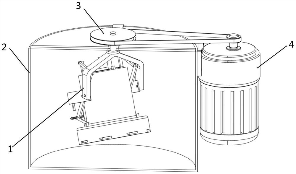
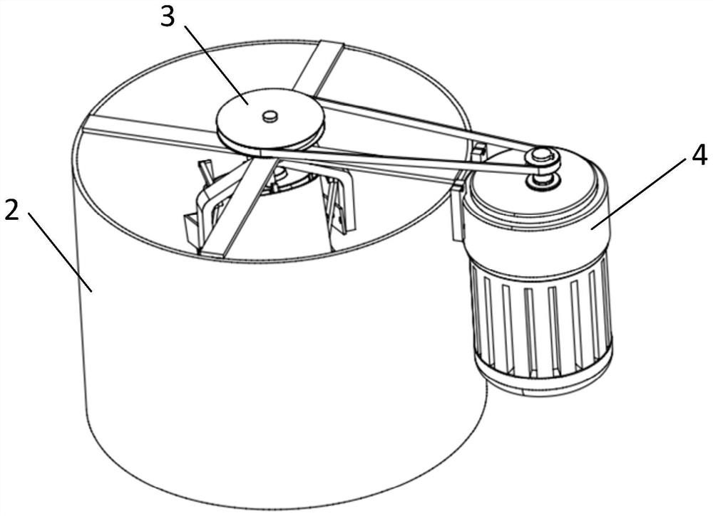
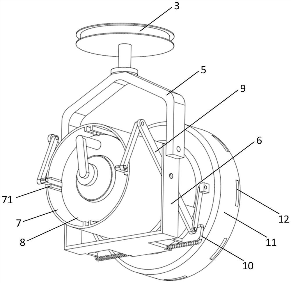
The invention discloses a centrifugal concrete slump testing device which comprises a centrifugal suspension slump cylinder, and the centrifugal suspension slump cylinder comprises a fork arm, a bracket, a concrete slump outer cylinder, a concrete slump inner cylinder, a connecting rod mechanism and a concrete slump bottom cylinder; the fork arm is connected with the bracket through a pin shaft I; the bracket is fixedly arranged on the outer wall of the concrete slump outer cylinder through a pin shaft II; a concrete slump bottom cylinder is arranged at the bottom of the concrete slump outer cylinder, and the concrete slump outer cylinder and the concrete slump bottom cylinder are of an integrated structure; a sliding groove is formed in the inner wall of the concrete slump outer cylinder, a sliding rail is arranged on the outer wall of the concrete slump inner cylinder, and the concrete slump outer cylinder and the concrete slump inner cylinder are in sliding fit. The spring bayonet lock is arranged at the connecting rod mechanism, the concrete slump inner cylinder is pre-fixed through the spring bayonet lock, and the viscosity data of the viscous concrete are compared by comparing the overflow amount of the viscous concrete with different components at the same rotating speed.

Description

technical field [0001] The invention relates to a device structure for concrete slump testing, belonging to the technical field of concrete testing, in particular to a centrifugal concrete slump testing device. Background technique [0002] Concrete slump mainly refers to the plasticizing performance and pumpability of concrete. The factors affecting concrete slump mainly include gradation changes, water content, weighing deviation of weighing instruments, and the amount of admixtures, which are easily overlooked. temperature of cement, etc. Slump refers to the workability of concrete, specifically to ensure the normal progress of construction, including the water retention, fluidity and cohesion of concrete. [0003] With the development of new material technology, the application of adding new materials to concrete to obtain modified concrete properties is becoming more and more common; Insufficient strength and other problems affect its safety and use function. In pract...

Claims


Application Information

Patent Timeline
IPC IPC(8): G01N33/38
CPCG01N33/383Y02W30/91
Inventor 董轶王建涛冯雷龚晓彤
Owner CHINA RAILWAY 18TH BUREAU GRP CO LTD
Learn More