Cable protection box for electrical engineering

A technology of electrical engineering and protection box, applied in electrical components, climate change adaptation, fire rescue, etc., to facilitate maintenance, reduce the probability of burnout, and avoid fires

Active Publication Date: 2022-07-08
CHONGQING UNIV
View PDF6 Cites 1 Cited by
  • Summary
  • Abstract
  • Description
  • Claims
  • Application Information

AI Technical Summary

Problems solved by technology

[0004] The object of the present invention is to provide a cable protection box for electrical engineering to solve the technical problems in the background technology

Method used


Image

  • Cable protection box for electrical engineering
  • Cable protection box for electrical engineering
  • Cable protection box for electrical engineering

Examples


Embodiment 1

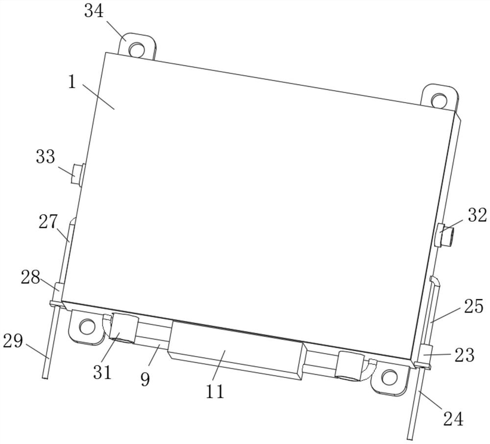
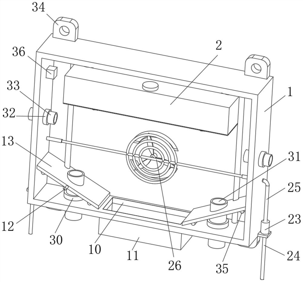
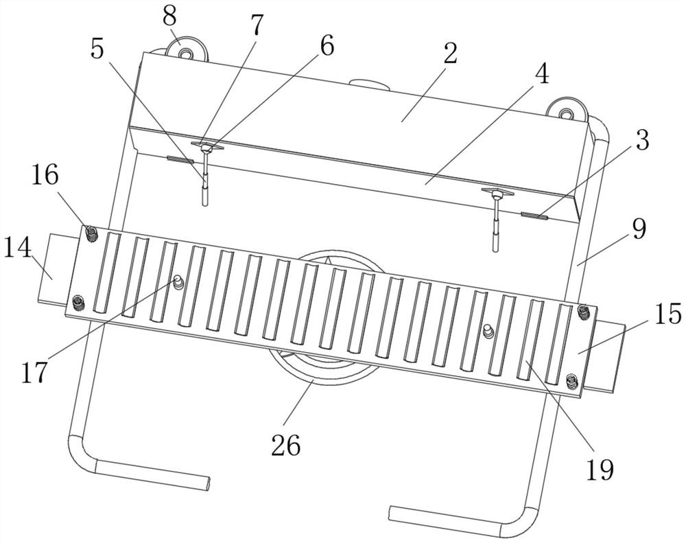
[0028] see Figure 1-7 As shown, the present invention provides a technical solution: a cable protection box for electrical engineering, comprising a protection box 1 and a first mounting plate 15, the inner wall of the protection box 1 is fixedly connected with a dry powder box 2, and the outer wall of the dry powder box 2 is provided with There is a hinge 3, the outer wall of the hinge 3 is hinged with a bottom plate 4, the bottom outer wall of the bottom plate 4 is fixedly connected with a mounting seat 7, the inner wall of the mounting seat 7 is provided with a rotating ball 6, and the inner wall of the protection box 1 is fixedly connected with an electric push rod 5 , the end of the electric push rod 5 away from the protection box 1 is fixedly connected with the outer wall of the rotating ball 6, the top outer wall of the dry powder box 2 is fixedly connected with a negative pressure machine 8, and the input end of the negative pressure machine 8 is fixedly connected with...

Embodiment 2

[0031] see Figure 1-7 As shown, on the basis of the first embodiment, the present invention provides a technical solution: the outer walls on both sides of the first installation plate 15 are fixedly connected with the fixing plates 14, and the outer wall of the fixing plate 14 away from the first installation plate 15 is connected to the outer wall of the side. The inner wall of the protection box 1 is fixedly connected, the outer wall of the first mounting plate 15 is fixedly connected with a spring 16, the end of the spring 16 away from the first mounting plate 15 is fixedly connected with a second mounting plate 18, and the outer wall of the first mounting plate 15 is fixedly connected with a second mounting plate 18. The telescopic rod 17, the end of the telescopic rod 17 away from the first mounting plate 15 is fixedly connected to the outer wall of the second mounting plate 18, and the outer wall of the first mounting plate 15 and the second mounting plate 18 close to e...

Embodiment 3

[0034] see Figure 1-7As shown, on the basis of Embodiment 1 and Embodiment 2, the present invention provides a technical solution: a motor 20 is fixedly connected to the inner wall of the protection box 1 , a fan 22 is fixedly connected to the output end of the motor 20 , and the outer wall of the protection box 1 is fixedly connected with a fan 22 . A heat dissipation groove 21 is opened on the outer side of the motor 20 , a first water pump 23 is fixedly connected to one outer wall of the protection box 1 , the input end of the first water pump 23 is fixedly connected with a first water pipe 24 , and the output end of the first water pump 23 is fixed A second water pipe 25 is connected, the end of the second water pipe 25 away from the first water pump 23 is fixedly connected with a through-flow pipe 26, and the outer wall of the protection box 1 away from the first water pump 23 is fixedly connected with a second water pump 28, the second water pump 28 The input end of the...


PUM


Abstract

The invention discloses a cable protection box for electrical engineering, and relates to the technical field of electrical engineering. Comprising a protection box and a first mounting plate, a dry powder box is fixedly connected to the inner wall of the protection box, a hinge is arranged on the outer wall of the dry powder box, a bottom plate is hinged to the outer wall of the hinge, a mounting seat is fixedly connected to the outer wall of the bottom of the bottom plate, a rotating ball is arranged on the inner wall of the mounting seat, and an electric push rod is fixedly connected to the inner wall of the protection box. The bottom plate is hinged to the dry powder box through a hinge, the interior of the protection box is monitored in real time through a flame sensor, when a cable is burnt out to cause a fire, the flame sensor transmits a signal to a controller of the protection box in time, then an electric push rod is contracted, and the bottom plate is driven to be opened through matched use of a rotating ball and a mounting base; at the moment, the dry powder in the dry powder box can rapidly extinguish the position where the cable is on fire, fire disasters are avoided, and losses caused by burning loss of the cable are reduced.

Description

technical field [0001] The invention belongs to the technical field of electrical engineering, and in particular relates to a cable protection box for electrical engineering. Background technique [0002] Cable is a general term for optical cables, cables and other items. It is mainly used for multiple functions such as control installation, connection equipment, and power transmission. It is a common and indispensable thing in daily life. mature, and cables are increasingly used in electrical engineering. [0003] At present, the existing protection devices on the market can only protect the single cable, and cannot protect and comb the cables in dense places, which leads to the direct contact between multiple cables stacked together, which is easy to generate large heat. When the temperature of the cable cannot be evacuated in time, it is easy to cause the burning of the cable, and in severe cases, a fire will occur, resulting in unnecessary losses. SUMMARY OF THE INVEN...

Claims


Application Information

Patent Timeline
Patent Type & Authority Applications(China)
IPC IPC(8): H02G3/08H02G3/03A62C35/02A62C35/62A62C37/36
CPCH02G3/08H02G3/088H02G3/03A62C35/02A62C35/62A62C37/36Y02A30/14
Inventor 郑贞恒王世琦钱奕婷崔哲
Owner CHONGQING UNIV
Why Eureka
Try Eureka