
Height shaping and adjusting clamp for cold heading thin-wall sleeve part

A casing and thin-walled technology is applied in the field of height shaping and adjusting fixtures for cold heading thin-walled casing parts, which can solve the problem that the finished product cannot reach the pre-determined precision, and achieve the effect of increasing the force-bearing area and enhancing the cleaning effect. tight fit

Pending Publication Date: 2022-07-12
苏州富力诚精密部件有限公司
View PDF0 Cites 0 Cited by
  • Summary
  • Abstract
  • Description
  • Claims
  • Application Information

AI Technical Summary

Problems solved by technology

[0005] In order to make up for the deficiencies of the existing technology and solve the problem that the finished product after processing is likely to fail to reach the precision preset value due to the lack of height shaping adjustment fixtures during the shaping of cold heading thin-walled casing parts, the invention proposes a cold heading Height shaping adjustment fixture for upsetting thin-wall casing parts

Method used


Image

  • Height shaping and adjusting clamp for cold heading thin-wall sleeve part
  • Height shaping and adjusting clamp for cold heading thin-wall sleeve part
  • Height shaping and adjusting clamp for cold heading thin-wall sleeve part

Examples


Embodiment 1

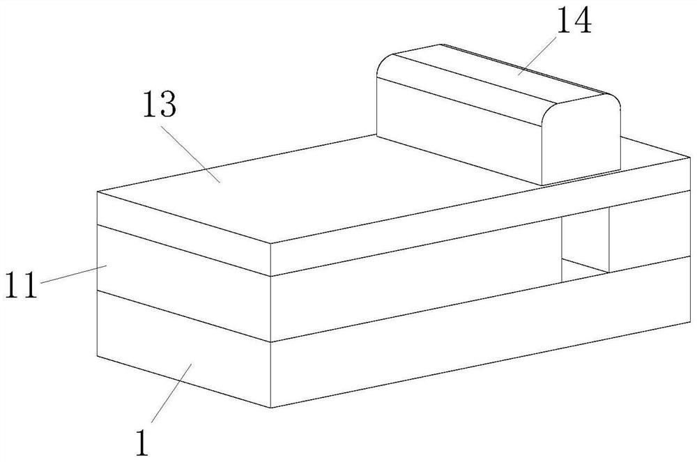
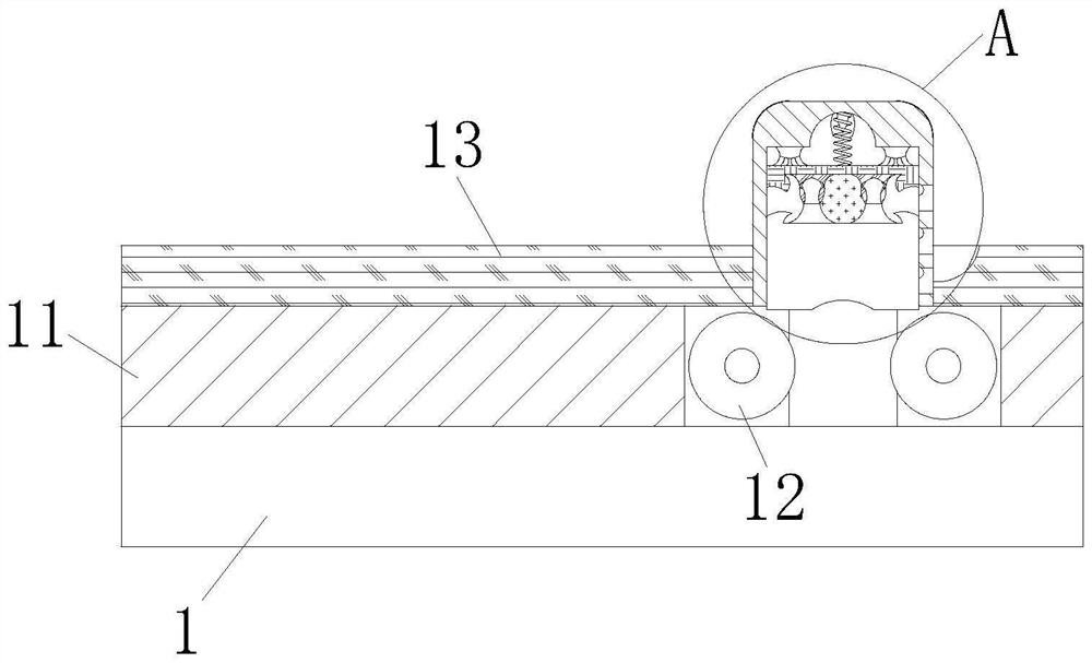
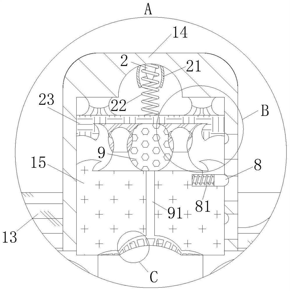
[0030] see Figure 1-6 As shown, a height shaping adjustment fixture for cold heading thin-walled casing parts includes a base bottom plate 1 and an adjustment unit; the adjustment unit is arranged at the end of the base bottom plate 1; the end of the base bottom plate 1 A guide plate 11 is fixedly connected; the inner side wall of the guide plate 11 is rotatably connected with two sets of righting bullets 12; the adjustment unit includes a height-limiting cover plate 13, a height-limiting shaping block 14, a sliding pressure plate 15 and an auxiliary mechanism; The height-limiting cover plate 13 is arranged at the end of the righting bullet 12 ; the height-limiting shaping block 14 is fixedly connected to the inner side wall of the height-limiting cover plate 13 ; the sliding pressure plate 15 is slidably connected to the inner side of the height-limiting shaping block 14 The bottom end of the sliding pressing plate 15 is provided with an arc-shaped groove; the auxiliary mech...

Embodiment 2

[0040] see Figure 7 As shown, in Comparative Example 1, as another embodiment of the present invention, the bottom end of the sliding pressure plate 15 is fixedly connected with a friction pad 98; the shape of the friction pad 98 corresponds to the bottom end of the sliding pressure plate 15; During operation, the friction pad 98 at the bottom end of the sliding pressure plate 15 is pressed against the end of the sleeve, and the friction pad 98 protects the sleeve and prevents friction to the bottom side wall of the sliding pressure plate 15 .

[0041] Working principle, when working, the staff puts the sleeve into the side wall of the guide plate 11, and is located between the two sets of righting warheads 12, and the height-limiting cover plate 13 is driven by the electric cylinder to press down on the end of the guide plate 11. position, the sliding pressure plate 15 inside the height-limiting shaping block 14 is pressed against the end of the casing, and cooperates with t...


PUM


Abstract

The invention belongs to the field of sleeve machining, and particularly relates to a cold heading thin-wall sleeve part height shaping and adjusting clamp which comprises a base bottom plate and an adjusting unit. The adjusting unit is arranged at the end part of the base bottom plate; the end part of the base bottom plate is fixedly connected with a guide protection plate; the inner side wall of the guide and protection plate is rotationally connected with two sets of righting warheads. The adjusting unit comprises a height-limiting cover plate, a height-limiting shaping block, a sliding pressing plate and an auxiliary mechanism. Through the arranged adjusting unit, a casing pipe is placed between two sets of centralizing elastic heads, an electric cylinder drives a height limiting cover plate to press downwards, meanwhile, a sliding pressing plate is attached to the end of the casing pipe in a pressurized mode and slides on the inner side wall of a height limiting shaping block, a spring is matched with the pressing plate in an extrusion mode to slide, force is applied to the sliding pressing plate, the sliding pressing plate is attached more tightly, and therefore the casing pipe can be well fixed. And the limiting block and the limiting cylinder are matched to support the bottom end of the spring to limit the end part of the sleeve, so that the sleeve is prevented from violently shaking when being processed.

Description

technical field [0001] The invention relates to the field of casing processing, in particular to a height shaping and adjusting fixture for cold heading thin-wall casing parts. Background technique [0002] The mature traditional production process of cold heading thin-walled casing is purchasing wire rod, cold heading machine cold heading, double end face end grinding, vibration grinding sharp edge burr, surface treatment, CCD full inspection, packaging and shipping. [0003] The manufacturing process of the cold heading machine is to send the annealed and spheroidized coiled wire into the feeding port of the equipment, automatically shear the equal-weight and equal-shaped material sections, and then go through the multi-channel cold heading molds in the cold heading equipment. extension, shaping and through-hole. [0004] When the cold-headed thin-walled casing parts are reshaped, because the height shaping adjustment fixture is not equipped, the precision of the finished...

Claims


Application Information

Patent Timeline
Patent Type & Authority Applications(China)
IPC IPC(8): B21J5/08B21J13/08B21J13/10
CPCB21J5/08B21J13/10B21J13/085
Inventor 邓晨浩
Owner 苏州富力诚精密部件有限公司
Learn More