Shaft end photoelectric rotating speed sensor for rail transit and manufacturing method

A speed sensor and rail transit technology, which is applied in the field of rail transit, can solve problems such as unrealizable and application limitations of photoelectric speed sensors, and achieve the effects of improving assembly efficiency, realizing miniaturization, and solving leakage

Inactive Publication Date: 2022-07-12
NINGBO CRRC TIMES TRANSDUCER TECH CO LTD
View PDF15 Cites 0 Cited by
  • Summary
  • Abstract
  • Description
  • Claims
  • Application Information

AI Technical Summary

Problems solved by technology

[0004] However, the above-mentioned photoelectric speed sensor can only realize single-channel signal output, but cannot realize dual-channel or even multi-channel signal output, which limits the application of the photoelectric speed sensor.

Method used


Image

  • Shaft end photoelectric rotating speed sensor for rail transit and manufacturing method
  • Shaft end photoelectric rotating speed sensor for rail transit and manufacturing method
  • Shaft end photoelectric rotating speed sensor for rail transit and manufacturing method

Examples


Embodiment Construction

[0038] The following are specific embodiments of the present invention and combined with the accompanying drawings to further describe the technical solutions of the present invention, but the present invention is not limited to these embodiments.

[0039] It should be noted that all directional indications (such as up, down, left, right, front, back, etc.) in the embodiments of the present invention are only used to explain the relationship between various components under a certain posture (as shown in the accompanying drawings). The relative positional relationship, the movement situation, etc., if the specific posture changes, the directional indication also changes accordingly.

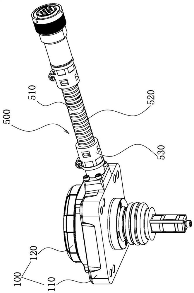
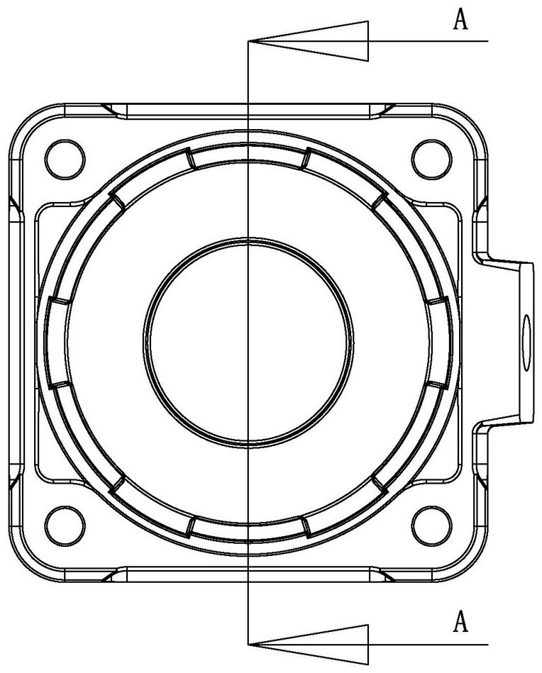
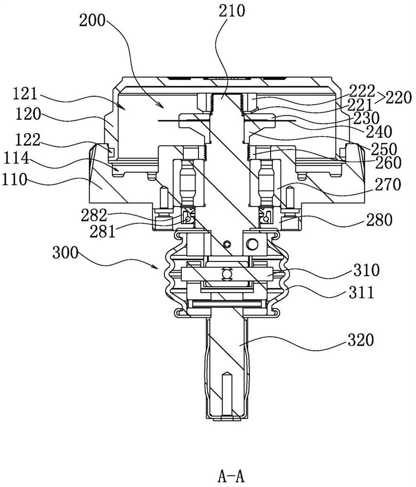
[0040] like Figure 1 to Figure 6 As shown, the present invention provides a shaft end photoelectric speed sensor for rail transit, comprising:

[0041] The carrier 100 includes a base 110 and a cover 120 connected with the base 110 by fasteners, wherein a cavity is formed by splicing the base 1...


PUM


Abstract

The invention provides a shaft end photoelectric rotating speed sensor for rail transit and a manufacturing method, and belongs to the technical field of rail transit, and the shaft end photoelectric rotating speed sensor comprises a carrier which comprises a device seat and an outer cover connected with the device seat through a fastener, and the device seat and the outer cover are spliced to form a cavity; one end of the mechanical rotating module extends into the cavity, and the other end of the mechanical rotating module penetrates through the device base and is matched with a train axle in an inserting manner; the signal acquisition module at least comprises a signal acquisition unit, the signal acquisition unit comprises a signal acquisition shell connected to the device base, two signal acquisition devices are installed in the signal acquisition shell, and the output ends of the two signal acquisition devices extend out of the signal acquisition shell and are aligned with the grating sheet; and the signal transmission module is connected to the device seat through a fastener. According to the invention, two signal collectors are arranged in the signal acquisition module, so that the output of dual-channel signals is realized.

Description

technical field [0001] The invention belongs to the technical field of rail transit, and relates to a photoelectric rotational speed sensor, in particular to a shaft end photoelectric rotational speed sensor for rail transit and a manufacturing method. Background technique [0002] The photoelectric speed sensor is installed on the shaft end of various types of locomotives to provide the running speed and movement direction of the locomotive, and is an important part of the safe operation of the locomotive. The input shaft of the sensor is connected with the axle to be measured, and the axle to be measured drives the input shaft of the sensor to rotate. The rotational speed of the axle to be measured is equal to the rotational speed of the input shaft. Using the photoelectric effect of the photoelectric module, an electrical pulse signal proportional to the rotational speed of the wheel is generated to realize the speed measurement. . [0003] Chinese patent (CN202204824U) ...

Claims


Application Information

Patent Timeline
Patent Type & Authority Applications(China)
IPC IPC(8): B23P21/00G01P1/00G01P1/02G01P3/36
CPCB23P21/00G01P3/36G01P1/00G01P1/026
Inventor 吴承书吕阳刘丹张燕亮郑华雄郑良广吴丽萍庞宇龙杨敏
Owner NINGBO CRRC TIMES TRANSDUCER TECH CO LTD
Why Eureka
Try Eureka