Cross double-channel lens barrel mold structure and forming method thereof

A dual-flow, cross-shaped technology, applied in glass production and other directions, can solve the problems of deviation in mold injection, different injection pressures at injection time, and inability to fix molds, so as to improve efficiency, improve consistency, and ensure injection quality. Effect

Active Publication Date: 2022-07-12
HUBEI HUAXIN PHOTOELECTRIC CO LTD
View PDF6 Cites 2 Cited by
  • Summary
  • Abstract
  • Description
  • Claims
  • Application Information

AI Technical Summary

Problems solved by technology

[0002] The mobile phone lens barrel is one of the components of the mobile phone lens. It is mainly manufactured by injection molding. When injecting the mobile phone lens barrel, an injection mold is needed, and the existing mold structure is mostly eight holes and one font. Arrangement, the advantage of this structure is that the structure is relatively compact and the material is relatively saved, but due to the difference in the distance from each hole to the glue inlet, this leads to the difference in the glue feeding time and glue feeding pressure of each hole, which leads to Product consistency is not good
[0003] In addition, during injection molding, since the mold needs to be placed between the upper and lower templates for thermal insulation and fixing, and the template at the top is mostly lifted by a hydraulic structure, when the pressure of the hydraulic structure is insufficient, the upper and lower templates cannot perform a good job on the mold. The fixation of the mold will cause the deviation of the mold during injection molding, which will affect the injection quality of the product

Method used


Image

  • Cross double-channel lens barrel mold structure and forming method thereof
  • Cross double-channel lens barrel mold structure and forming method thereof
  • Cross double-channel lens barrel mold structure and forming method thereof

Examples


Embodiment Construction

[0038] In order to make the purposes, technical solutions and advantages of the embodiments of the present invention clearer, the technical solutions in the embodiments of the present invention will be clearly and completely described below with reference to the accompanying drawings in the embodiments of the present invention. Obviously, the described embodiments These are some embodiments of the present invention, but not all embodiments. Based on the embodiments of the present invention, all other embodiments obtained by those of ordinary skill in the art without creative efforts shall fall within the protection scope of the present invention.

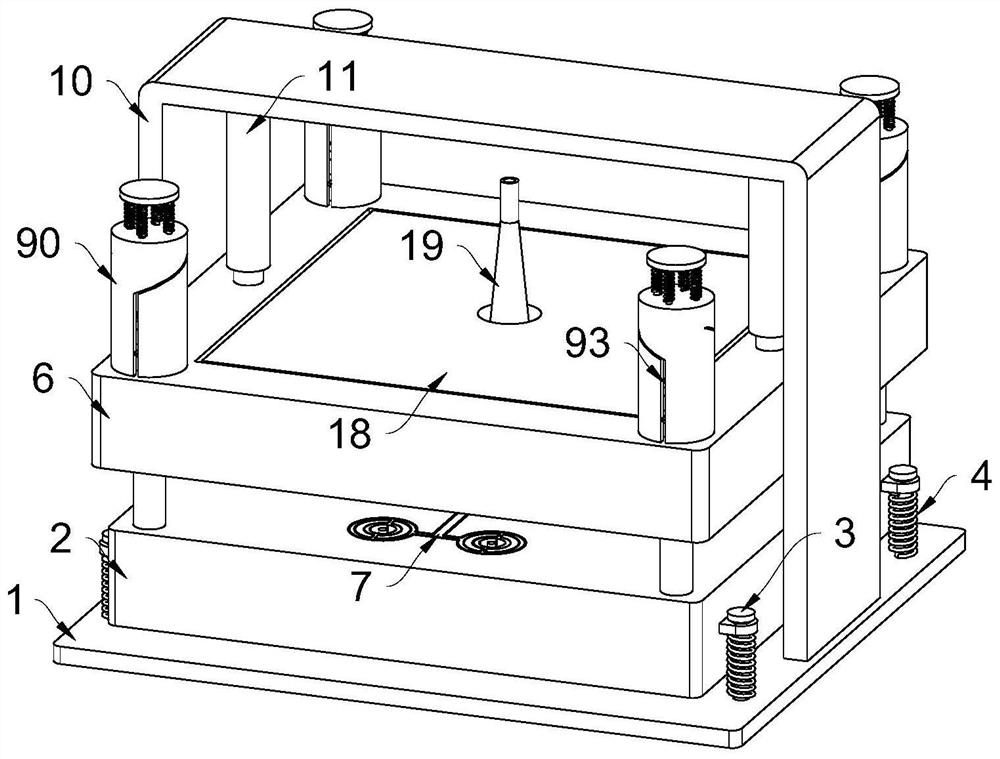
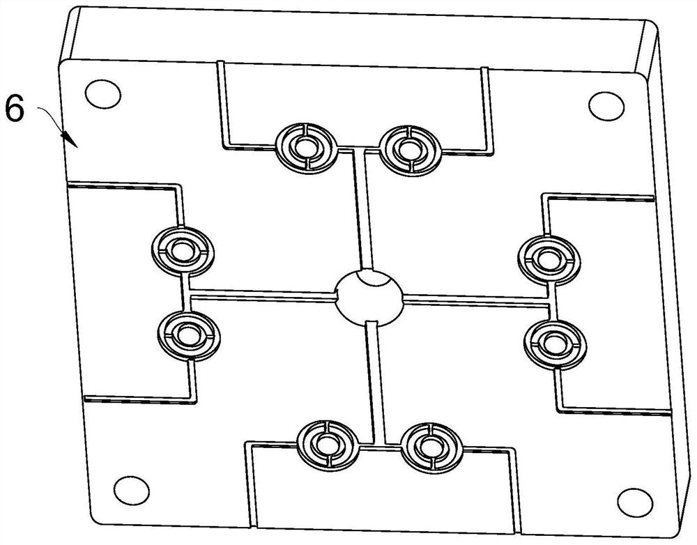
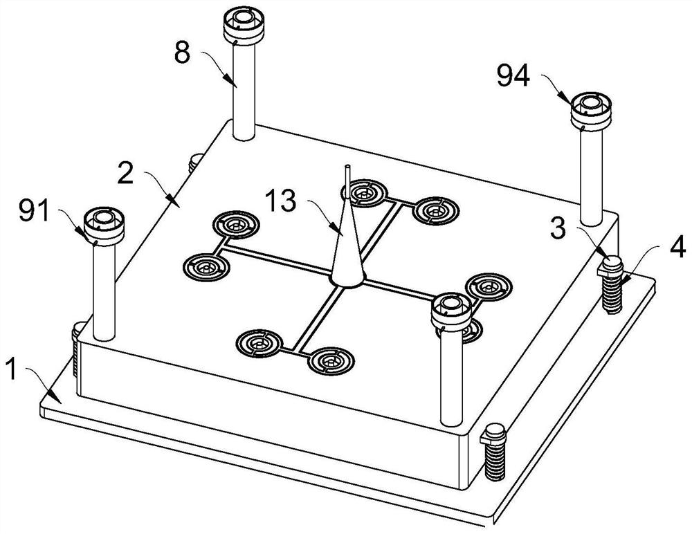
[0039] The present invention provides such as Figure 1-Figure 12 A cross-shaped double-channel lens barrel mold structure shown includes a base 1, and a lower template 2 is provided on the top of the base 1, and two fixing plates are fixedly connected to both sides of the lower template 2. A sliding rod 3 is inserted through the u...


PUM


Abstract

The invention belongs to the technical field of lens cone molds, and particularly relates to a cross-shaped double-flow-channel lens cone mold structure which comprises a base, a lower mold plate is arranged at the top of the base, two fixing plates are fixedly connected to the two sides of the lower mold plate correspondingly, sliding rods are inserted into the fixing plates in a sliding and penetrating mode, and the sliding rods are fixedly connected with the base. The part, located at the bottom of the fixing plate, of the sliding rod is sleeved with a first spring, and a containing groove is formed in the bottom of the lower die plate. In the injection molding process, after injection molding glue enters the glue inlet pipe, due to the fact that the distances from the main injection molding pipe to the branch pipes are the same, the time and pressure of the injection molding glue entering all the first annular pipes are the same, and therefore the consistency of products can be conveniently improved; and then the injection molding glue entering the first annular pipe simultaneously enters the second annular pipe through the two symmetrical connecting pipes located on the outer side of the second annular pipe, so that compared with a traditional injection mold arranged in a straight line, the injection molding efficiency is improved.

Description

technical field [0001] The invention belongs to the technical field of lens barrel molds, and particularly relates to a cross-shaped double-flow channel lens barrel mold structure. Background technique [0002] The mobile phone lens barrel is one of the components of the mobile phone lens. It is mainly manufactured by injection molding. When the mobile phone lens barrel is injected, an injection mold is required, and the existing mold structure is mostly eight-hole and one-shaped. The advantage of this structure is that the structure is relatively compact and the material is saved. However, due to the difference in the distance from each hole to the glue inlet, the glue feeding time and glue feeding pressure of each hole are different, which leads to The consistency of the product is not good. [0003] In addition, during injection molding, since the mold needs to be placed between the upper and lower mold plates for heat preservation and fixation, the mold plate at the top...

Claims


Application Information

Patent Timeline
Patent Type & Authority Applications(China)
IPC IPC(8): B29C45/26B29C45/27B29C45/66B29C45/73
CPCB29C45/26B29C45/27B29C45/66B29C45/7337Y02P40/57
Inventor 冉强
Owner HUBEI HUAXIN PHOTOELECTRIC CO LTD
Why Eureka
Try Eureka