Adjustable mechanical hydraulic packing machine for production line

A mechanical hydraulic and adjustable technology, applied in the direction of presses, manufacturing tools, etc., can solve the problems of unadjustable extrusion depth and inconvenient unloading, so as to avoid material scatter, reduce trouble, and speed up unloading time Effect

Inactive Publication Date: 2022-07-12
湖南三一工业职业技术学院
View PDF1 Cites 0 Cited by
  • Summary
  • Abstract
  • Description
  • Claims
  • Application Information

AI Technical Summary

Problems solved by technology

[0005] In order to overcome the disadvantages that the existing hydraulic baler is inconvenient when unloading materials and the extrusion depth cannot be adjusted, the purpose of the present invention is to provide a production line that can not only adjust the extrusion depth but also facilitate and quickly unload. Adjustable mechanical hydraulic baler

Method used


Image

  • Adjustable mechanical hydraulic packing machine for production line
  • Adjustable mechanical hydraulic packing machine for production line
  • Adjustable mechanical hydraulic packing machine for production line

Examples


Embodiment 1

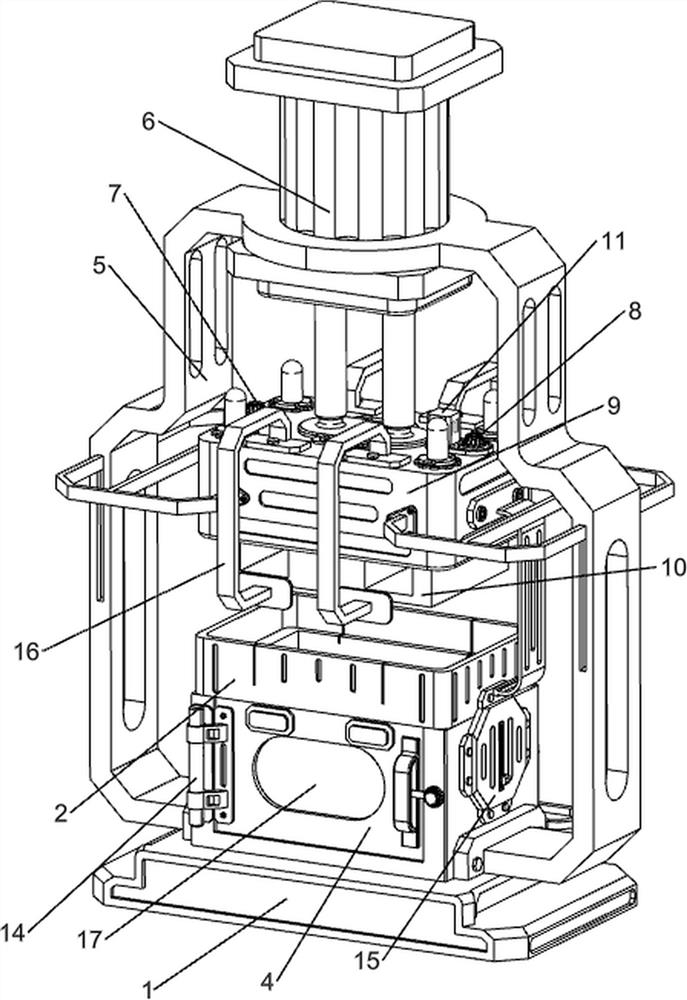
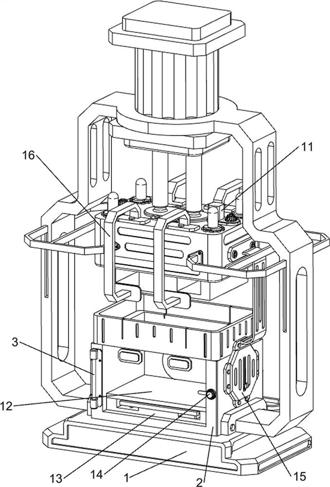
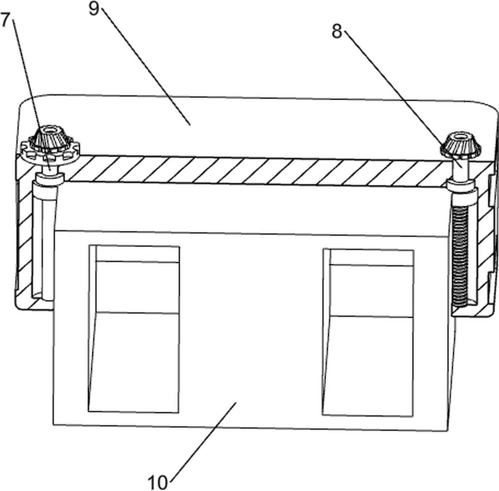
[0041] An adjustable mechanical hydraulic baler for production line, in Figure 1-3As shown in the figure, it includes a base plate 1, a placing frame 2, a rotating shaft 3, a protective door 4, a limit frame 5, a hydraulic cylinder 6, a guide rod 7, a threaded rod 8, a guide shell 9, a pressing block 10, a transmission mechanism 11, a collection The mechanism 12 and the transparent plate 17, the top of the bottom plate 1 is bolted with a placing frame 2, the left side of the placing frame 2 is symmetrically connected with a rotating shaft 3 through bolts, and the rotating shaft 3 is equipped with a rotating protective door 4, and the protective door 4 is connected with the placing frame. 2 contact, a transparent plate 17 is arranged in the middle of the protective door 4, a limit frame 5 is connected between the left and right side walls of the placing frame 2, a hydraulic cylinder 6 is installed on the upper part of the limit frame 5, and the bottom of the two telescopic rods...

Embodiment 2

[0047] On the basis of Example 1, in figure 2 , Figure 8 , Figure 9 , Figure 10 , Figure 11 and Figure 12 It also includes a snap mechanism 13, and the snap mechanism 13 includes a support plate 130, a top block 131, a wedge rod 132, a return spring 133, a snap plate 134, a return spring 135 and a connecting frame 136, which are placed in the frame 2 A support plate 130 is welded at the bottom, a top block 131 is provided on the inner side of the lower part of the protective door 4, and wedge-shaped rods 132 are slidably provided on the left and right sides of the support plate 130. A return spring 133 is connected between the rod 132 and the interior of the support plate 130 , the left and right sides of the support plate 130 are slidably provided with a clamping plate 134 that can play a fixed role, and the wedge-shaped rods 132 are slidingly matched with the adjacent clamping plates 134 Two return springs 135 are connected between the clamping plate 134 and the s...


PUM


Abstract

The invention relates to a packing machine, in particular to an adjustable mechanical hydraulic packing machine for a production line. According to the adjustable mechanical hydraulic packing machine for the production line, the extrusion depth can be adjusted, and discharging is convenient and rapid. An adjustable mechanical hydraulic packing machine for a production line comprises a bottom plate, a containing frame, rotating shafts, protective doors, a limiting frame, a hydraulic cylinder, a guide shell and the like, the containing frame used for containing materials is arranged at the top of the bottom plate, the rotating shafts are symmetrically arranged on the left side of the containing frame in the front-back direction, and the protective doors used for protection are rotationally arranged on the rotating shafts. A limiting frame is connected between the left side wall and the right side wall of the containing frame, a hydraulic cylinder is arranged on the upper portion of the limiting frame, and a guide shell is connected between the bottoms of two telescopic rods of the hydraulic cylinder. And after the materials are extruded, people directly pull out the placing plate, the materials can be taken out, then the materials are collected, scattering of the materials is avoided, and the discharging time is shortened.

Description

technical field [0001] The invention relates to a hydraulic baler, in particular to an adjustable mechanical hydraulic baler for production lines. Background technique [0002] Hydraulic balers are mainly used in steel mills, crop straw, recycling and processing industries and non-ferrous and ferrous metal smelting industries. The hydraulic baler can extrude various metal scraps into various shapes such as cuboid and octagon, which can reduce transportation and smelting costs. The fabric is packed in boxes for easy sale and transportation. [0003] The application number is CN202020758311.5, and the publication number is CN213441323U, a hydraulic baler with mobile capability, including a first bidirectional motor, a universal wheel, a support plate, a rotating threaded column, a fixed seat, a limit cylinder, a support roller and a lift A fixed seat is installed symmetrically on the left and right end faces of the stable base, a first bidirectional motor is installed in the...

Claims


Application Information

Patent Timeline
Patent Type & Authority Applications(China)
IPC IPC(8): B30B9/30B30B15/00B30B15/32B30B15/22
CPCB30B9/3057B30B9/3003B30B9/3014B30B15/22
Inventor 周志宏周祺畅何柳舒莉陈海媚刘璐何超波
Owner 湖南三一工业职业技术学院
Why Eureka
Try Eureka