Rotary crane device

A technology of slewing platform and slewing mechanism, which is applied in hoisting devices, cranes, hydroelectric power generation, etc. It can solve problems such as low hoisting accuracy and efficiency, large sloshing, and inability to ensure automatic and precise positioning of gates into slots, etc., to improve installation Convenience, easy installation, and the effect of improving hoisting efficiency

Pending Publication Date: 2022-07-12
SINOHYDRO JIAJIANG HYDRAULIC MACHINERY +1
View PDF1 Cites 2 Cited by
  • Summary
  • Abstract
  • Description
  • Claims
  • Application Information

AI Technical Summary

Problems solved by technology

However, in the process of hoisting the gate, the shaking is relatively large, and the automatic and precise positioning of the gate into the slot cannot be guaranteed, and the hoisting accuracy and hoisting efficiency are low.

Method used


Image

  • Rotary crane device
  • Rotary crane device
  • Rotary crane device

Examples


Embodiment 1

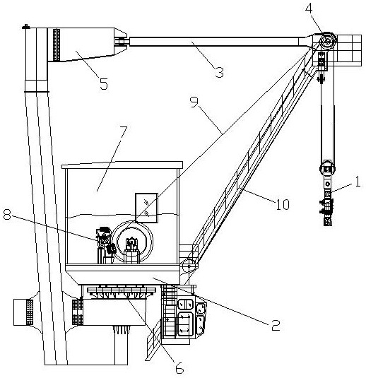
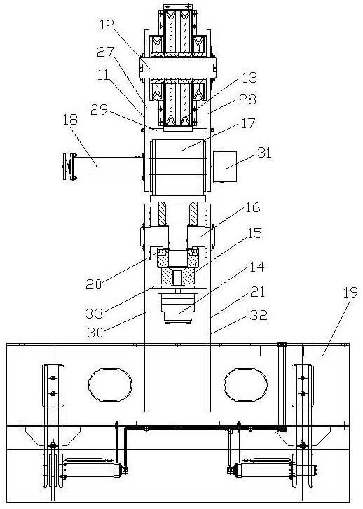
[0031] see figure 1 and figure 2 , a slewing hoisting device, including a spreader 1, a slewing platform 2, a pull rod 3, a pulley block 4, a slewing mechanism 6 installed under the gantry 5 and a slewing machine room 7 installed on the slewing mechanism 6 through the slewing platform 2, the slewing machine room A hoisting mechanism 8 is installed in 7, a wire rope 9 is wound on the hoisting mechanism 8, a boom 10 is installed on the slewing machine room 7, the pulley block 4 is installed on the top of the boom 10, and one end of the pull rod 3 is hinged with the top of the gantry 5 , the other end of the pull rod 3 is hinged with the arm frame 10, and the hanger 1 includes an upper hanger 11, a pulley shaft 12, a movable pulley block 13, a pin 18, a lifting head 17, a lower hanger 21, a hook beam 16, a hanger The hook nut 15, the rotary drive member 14 and the grab beam 19, the movable pulley block 13 is installed on the upper hanger 11 through the pulley shaft 12, and the ...

Embodiment 2

[0034] see figure 1 and figure 2, a slewing hoisting device, including a spreader 1, a slewing platform 2, a pull rod 3, a pulley block 4, a slewing mechanism 6 installed under the gantry 5 and a slewing machine room 7 installed on the slewing mechanism 6 through the slewing platform 2, the slewing machine room A hoisting mechanism 8 is installed in 7, a wire rope 9 is wound on the hoisting mechanism 8, a boom 10 is installed on the slewing machine room 7, the pulley block 4 is installed on the top of the boom 10, and one end of the pull rod 3 is hinged with the top of the gantry 5 , the other end of the pull rod 3 is hinged with the arm frame 10, and the hanger 1 includes an upper hanger 11, a pulley shaft 12, a movable pulley block 13, a pin 18, a lifting head 17, a lower hanger 21, a hook beam 16, a hanger The hook nut 15, the rotary drive member 14 and the grab beam 19, the movable pulley block 13 is installed on the upper hanger 11 through the pulley shaft 12, and the m...

Embodiment 3

[0040] see Figure 1-Figure 3 , a slewing hoisting device, including a spreader 1, a slewing platform 2, a pull rod 3, a pulley block 4, a slewing mechanism 6 installed under the gantry 5 and a slewing machine room 7 installed on the slewing mechanism 6 through the slewing platform 2, the slewing machine room A hoisting mechanism 8 is installed in 7, a wire rope 9 is wound on the hoisting mechanism 8, a boom 10 is installed on the slewing machine room 7, the pulley block 4 is installed on the top of the boom 10, and one end of the pull rod 3 is hinged with the top of the gantry 5 , the other end of the pull rod 3 is hinged with the arm frame 10, and the hanger 1 includes an upper hanger 11, a pulley shaft 12, a movable pulley block 13, a pin 18, a lifting head 17, a lower hanger 21, a hook beam 16, a hanger The hook nut 15, the rotary drive member 14 and the grab beam 19, the movable pulley block 13 is installed on the upper hanger 11 through the pulley shaft 12, and the movab...


PUM


Abstract

The invention discloses a rotary lifting device, which belongs to the technical field of lifting opening and closing equipment, comprises a lifting appliance, and is characterized in that the lifting appliance comprises an upper lifting frame, a pulley shaft, a movable pulley block, a pin penetrating piece, a lifting head, a lower lifting frame, a lifting hook cross beam, a lifting hook nut, a rotary driving piece and a grabbing beam, the lifting head is fixed on the upper lifting frame through a pin penetrating piece, the lifting hook cross beam penetrates through the lifting hook nut and is arranged on the lower lifting frame, the lifting hook nut is connected with the lifting head, the rotary bearing is arranged between the lifting hook cross beam and the lifting hook nut, the rotary driving piece is arranged on the lower lifting frame, and the grabbing beam is connected with the lower lifting frame. The lifting appliance can synchronously and reversely rotate to ensure that the axis of a gate is always parallel to the axis of a gate groove, and the lifting appliance and the gate are prevented from shaking in the rotation process, so that the gate can be automatically and accurately positioned into the groove, the lifting precision and the lifting efficiency are improved, and the whole rotation lifting appliance is convenient to mount.

Description

technical field [0001] The invention relates to the technical field of lifting, restarting and closing equipment, in particular to a slewing hoisting device. Background technique [0002] Among the existing hoisting equipment, especially the hoisting and closing equipment that uses slewing hoist to hoist objects and needs to be accurately positioned, such as the hoist of a hydropower station to hoist the gate entry slot or entry storehouse. [0003] Since the operation mode of the slewing mechanism is rotary motion, the trajectory and the tangential angle of each door slot or door magazine are different during its operation, so that the axis of the door body cannot be kept with the axis of the door slot and door magazine to be placed during the lifting process. Parallel, even if the wire rope does not swing, it is difficult for the gate to enter the groove without other forces. Therefore, the existing lifting equipment needs manual auxiliary operation to realize the precise...

Claims


Application Information

Patent Timeline
IPC IPC(8): B66C23/84B66C23/62B66D1/12B66D1/28
CPCB66C23/84B66C23/62B66D1/12B66D1/28Y02E10/20
Inventor 范如谷谭晓波李欣欣夏家泉黎悟非张建
Owner SINOHYDRO JIAJIANG HYDRAULIC MACHINERY
Why Eureka
Try Eureka