
Sediment starting flow velocity measuring device

A technology of flow velocity measurement and sediment start-up, which is applied in the direction of measuring device, fluid velocity measurement, velocity/acceleration/impact measurement, etc. It can solve the problems of measuring vertical average flow velocity, device layout, installation difficulty, and inaccurate measurement results, etc.

Active Publication Date: 2022-07-12
WUHAN UNIV
View PDF13 Cites 0 Cited by
  • Summary
  • Abstract
  • Description
  • Claims
  • Application Information

AI Technical Summary

Problems solved by technology

However, the judgment standards of different people cannot be exactly the same, which makes the measurement results have obvious individual differences
[0005] (2) Most conventional flow velocity measurement devices can only measure the flow velocity of a certain point or a small water column at a certain moment (this type of flow velocity measurement device belongs to the "point type" type ), it is impossible to obtain the average flow velocity of the vertical line at this moment; if the method of arranging multiple "point" type devices along the vertical line is used to measure the average flow velocity of the vertical line, the measurement results are often different due to multiple measuring devices. The disturbance of the water flow is too large or the mutual interference between the devices leads to inaccurate measurement results; in addition, the number of measuring devices is large, the purchase cost will increase, and the device layout and installation in the actual measurement will become difficult
[0006](3) It is difficult to quickly and synchronously measure the vertical average flow velocity at the moment when the sediment starts

Method used


Image

  • Sediment starting flow velocity measuring device
  • Sediment starting flow velocity measuring device
  • Sediment starting flow velocity measuring device

Examples


Embodiment Construction

[0025] The technical solutions of the present invention will be clearly and completely described below with reference to the embodiments of the present invention. Obviously, the described embodiment is only one embodiment of the present invention, rather than all the embodiments. Based on the embodiments of the present invention, all other embodiments obtained by those of ordinary skill in the art without creative work fall within the protection scope of the present invention.

[0026] It should be noted that the embodiments of the present invention and the features of the embodiments may be combined with each other under the condition of no conflict.

[0027] The present invention will be further described below with reference to specific embodiments and accompanying drawings, but it is not intended to limit the present invention.

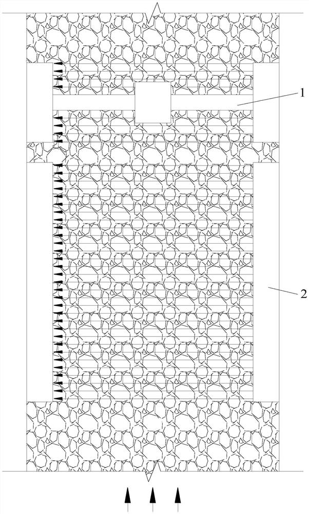
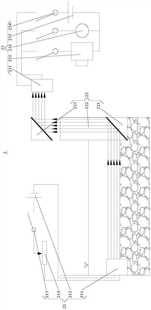
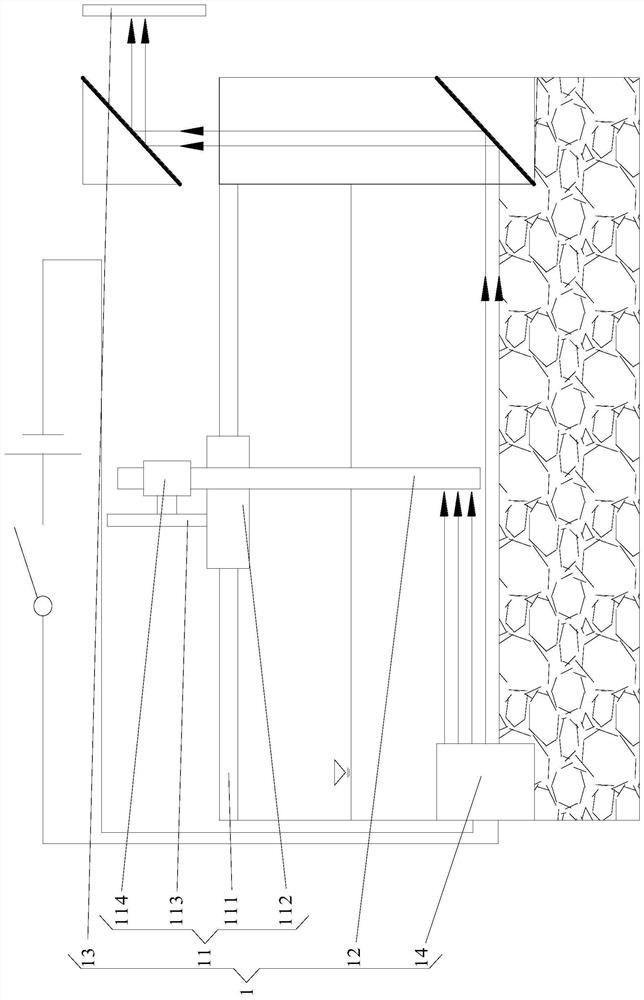
[0028] combine Figure 1 to Figure 4 As shown, a sediment starting flow velocity measuring device disclosed in the embodiment of the present inv...


PUM


Abstract

The invention provides a sediment starting flow velocity measuring device. The sediment starting flow velocity measuring device comprises a sediment starting sensing component and a flow velocity vertical line distribution measuring component, a flow velocity measurement control circuit of the flow velocity vertical line distribution measurement part comprises an electromagnet control circuit and a flow velocity display circuit. The electromagnet control circuit comprises a water baffle, a spring coil and an iron core; the flow velocity display circuit comprises a permanent magnet, a spring, a slide rheostat and an ammeter. When the water baffle is impacted by water flow, after a spring coil is compressed, the number of electrified coils surrounding an iron core is increased, then the magnetic force of an electromagnet is increased, and a permanent magnet is pushed to compress a spring, so that the access resistance of a slide rheostat is reduced, and the current of a corresponding branch is increased; as the flow velocity at each position on the flow velocity measuring rod is different, the current displayed by each ampere meter is different, so that the flow velocity at each vertical position can be output in the form of an electric signal, and the sediment starting flow velocity can be calculated according to the relationship between the current and the flow velocity.

Description

technical field [0001] The invention relates to the technical field of water and sand movement monitoring, in particular to a device for measuring the initial flow velocity of sediment. Background technique [0002] The static sediment particles on the river bed, with the enhancement of the water flow intensity, will start to move under certain conditions, this phenomenon is called sediment start. Sediment initiation is closely related to many problems in water transportation engineering. For example, in channel improvement, the most traditional method is to increase the flow rate by narrowing the channel to wash away excess sediment. In order to achieve this goal, we first need to clarify the flow conditions for the bed surface sediment to change from a static state to a moving state, that is, the sediment starting conditions. The starting condition of sediment is generally represented by the average velocity of the vertical line, which is called the starting velocity. ...

Claims


Application Information

Patent Timeline
Patent Type & Authority Applications(China)
IPC IPC(8): G01M10/00G01P5/08G01V8/10
CPCG01M10/00G01P5/086G01V8/10Y02A90/30
Inventor 潘云文夏军强周美蓉邓珊珊李启杰
Owner WUHAN UNIV
Learn More