Method and device for realizing target azimuth super-resolution
A target azimuth and super-resolution technology, which is applied to measuring devices, radio wave reflection/re-radiation, climate sustainability, etc., can solve problems such as inaccurate target azimuth angle information, and achieve accurate target azimuth angle information, high accuracy sexual effect
- Summary
- Abstract
- Description
- Claims
- Application Information
AI Technical Summary
Benefits of technology
Problems solved by technology
Method used
Image
Examples
Embodiment 1
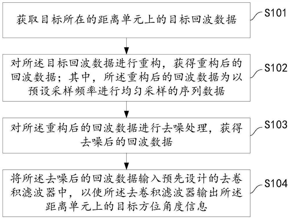
[0065] According to an embodiment of the present invention, a method for realizing super-resolution of target orientation is provided, such as figure 1 As shown, the method described in the embodiment of the present invention includes:
[0066] Step S101, acquiring target echo data on the distance unit where the target is located;
[0067] In this embodiment, the distance unit where the target is located is first determined by the following methods: receiving the echo signal of the target; performing pulse compression processing on the echo signal to obtain the echo signal after pulse pressure; The echo signal after the pulse pressure is sequentially processed by MTI (moving target indication), MTD (moving target detection) and CFAR (constant false alarm) to obtain the distance unit where the target is located.
[0068] Specifically, the echo signal of the target is the radar echo signal of the target. The radar echo signal of the target is modeled in advance. For a stationa...
Embodiment 2
[0121] Corresponding to the above method embodiments, the present invention also provides a device for realizing super-resolution of target azimuth, such as Figure 8 As shown, the device includes:
[0122] An echo data acquisition unit 201, configured to acquire target echo data on the distance unit where the target is located;
[0123] The reconstruction unit 202 is configured to reconstruct the target echo data to obtain reconstructed echo data; wherein, the reconstructed echo data is sequence data uniformly sampled at a preset sampling frequency ;
[0124] A denoising unit 203, configured to perform denoising processing on the reconstructed echo data to obtain denoised echo data;
[0125] Azimuth angle information acquisition unit 204, configured to input the denoised echo data into a pre-designed deconvolution filter, so that the deconvolution filter outputs the target azimuth angle information on the distance unit .
[0126] In this embodiment, the echo data acquisit...
Embodiment 3
[0158] According to an embodiment of the present invention, a storage medium is also provided, and program codes are stored on the storage medium, and when the program codes are executed by a processor, the realization of the target azimuth superposition according to any one of the foregoing embodiments is realized. method of distinguishing.
PUM
 Abstract
Description
Claims
Application Information
 - R&D
- Intellectual Property
- Life Sciences
- Materials
- Tech Scout
- Unparalleled Data Quality
- Higher Quality Content
- 60% Fewer Hallucinations
Browse by: Latest US Patents, China's latest patents, Technical Efficacy Thesaurus, Application Domain, Technology Topic, Popular Technical Reports.
© 2025 PatSnap. All rights reserved.Legal|Privacy policy|Modern Slavery Act Transparency Statement|Sitemap|About US| Contact US: help@patsnap.com


