Multi-angle steering photovoltaic tracking support

A multi-angle, photovoltaic technology, applied in the support structure of photovoltaic modules, photovoltaic power generation, photovoltaic modules, etc., can solve the problems of small increase in light utilization rate, large number of motors, and increased cost, so as to improve light energy utilization rate, Improve utilization and save resources

Pending Publication Date: 2022-07-12
天津中物绿色新能源科技有限公司
0 Cites 0 Cited by

AI-Extracted Technical Summary

Problems solved by technology

[0003] The existing self-adjusting angle photovoltaic support can only adjust the angle in the north-south direction. When the sun is slanting in the morning, morning and afternoon, the solar panel cannot rotate in the east-west direction, and can only absorb it to the greatest extent at noon. Solar energy, the overall light utilization rate is not greatly improved
[0004] Another problem is th...

Method used

As shown in Fig. 1-Fig. 2, a kind of multi-angle steering photovoltaic tracking support includes a column 1, a first rotating shaft 2 connected to the top of a plurality of parallel columns 1 in rotation, and also includes a vertical first rotating shaft 2 and rotates The second rotating shaft 3 connected to the first rotating shaft 2, wherein the top of the column 1 is provided with a first bearing seat 8, the first rotating shaft 2 is preferably a square cylinder, which can be connected with other parts with the largest contact area to enhance the connection Robustness, the first rotating shaft 2 is sleeved with a circular connecting collar, and the connecting collar is rotatably connected with the first bearing seat 8 . The top of the first rotating shaft 2 is provided with a second bearing seat 9, the second rotating shaft 3 is preferably a square cylinder, and a connecting collar with a circular outer wall is sleeved on the second rotating shaft 3, and the connecting collar and the second bearing seat 9 cooperate to rotate and connect.
Further, the rotation of the east-west direction of the photovoltaic tracking support of each row is driven by a second motor 13, the second motor 13 is fixed on the first rotating sha...

Abstract

The invention provides a multi-angle steering photovoltaic tracking support which comprises stand columns, a first rotating shaft rotationally connected to the tops of a plurality of parallel stand columns and a second rotating shaft perpendicular to the first rotating shaft and rotationally connected to the first rotating shaft, the first rotating shaft and the second rotating shaft are driven by a motor, and a purline is fixed to the second rotating shaft; the lower end of the first rotating shaft is fixedly connected with first swing arms, the free ends of the parallel first swing arms are rotationally connected with a transverse connecting rod, the lower end of the second rotating shaft is fixedly connected with second swing arms, and the free ends of the parallel second swing arms are rotationally connected with a longitudinal connecting rod. The photovoltaic tracking support can rotate in the north-south direction and the east-west direction, and the utilization rate of sunlight in the solar oblique illumination time period is increased; meanwhile, due to the effective connection of the structures between the rows, a plurality of rows of supports rotating in the south-north direction are driven by one motor, each row of supports rotating in the east-west direction is driven by one motor, resources are saved, and the cost is reduced.

Application Domain

Photovoltaic supportsSolar heating energy +3

Technology Topic

Electric machineryOblique illumination +3

Image

  • Multi-angle steering photovoltaic tracking support
  • Multi-angle steering photovoltaic tracking support

Examples

  • Experimental program(1)

Example Embodiment

[0018] The specific embodiments of the present invention will be described in detail below with reference to the accompanying drawings.
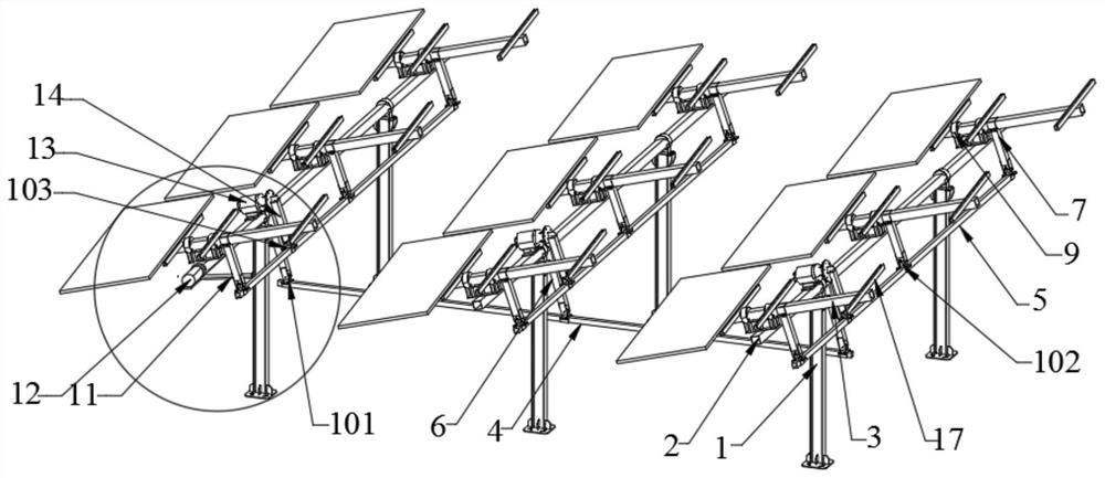
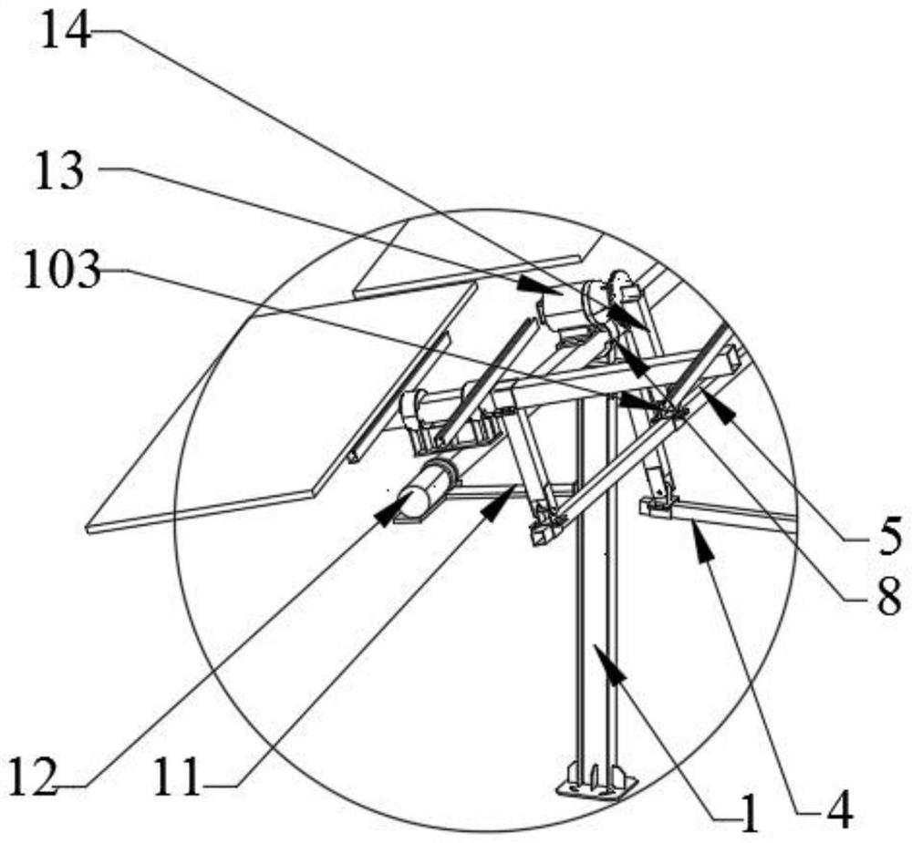
[0019] like Figure 1-Figure 2 As shown, a multi-angle steering photovoltaic tracking support includes a column 1, a first rotating shaft 2 rotatably connected to the tops of a plurality of parallel columns 1, and a first rotating shaft 2 that is perpendicular to the first rotating shaft 2 and is rotatably connected to the first rotating shaft 2. Two rotating shafts 3, wherein the top of the column 1 is provided with a first bearing seat 8, and the first rotating shaft 2 is preferably a square cylinder, which can be connected with other components with a maximum contact area to enhance the connection firmness, and the first rotating shaft 2 is sleeved A connecting collar with a circular outer wall is connected, and the connecting collar is rotatably connected with the first bearing seat 8 . The top of the first rotating shaft 2 is provided with a second bearing seat 9, the second rotating shaft 3 is preferably a square cylinder, the second rotating shaft 3 is sleeved with a circular connecting collar on the outer wall, the connecting collar and the second bearing seat 9 Fitted with rotating connection.
[0020] The first rotating shaft 2 and the second rotating shaft 3 are driven by a motor, and the purlins are vertically fixed on the second rotating shaft 3 . Preferably, the second purlins are composed of four parallel bars, and two solar panels are installed on the same second rotating shaft 3 .
[0021] The lower end of the first rotating shaft 2 is fixedly connected to the first swing arm 6, and the free ends of several parallel first swing arms 6 located in different rows are rotatably connected to the same transverse link 4, preferably, in order to increase the stability of the connection structure According to the length of the first rotating shaft 2, several transverse links 4 can be arranged under the multiple rows of the first rotating shaft 2, and the first rotating shaft 2 is connected to the transverse direction through the first swing arm 6. Rod 4 is connected in rotation.
[0022] The lower end of the second rotating shaft 3 is fixedly connected to the second swing arm 7 , and the free ends of several second swing arms 7 parallel to each other are rotatably connected to a longitudinal link 5 .
[0023] Wherein, the lower end of the first rotating shaft 2 is vertically arranged on the transverse link 4, a parallel lug plate is arranged at the free end of the first swing arm 6, and a first hinge seat 101 is arranged on the lower end of the transverse link 4. The first swing arm 6 It is rotatably connected to the hinge shaft on the first hinge seat 101 .
[0024] The longitudinal link 5 is arranged in parallel at the lower end of the first rotating shaft 2, the free end of the second swing arm 7 is provided with a parallel lug plate, the longitudinal link 5 at the lower end is arranged with a second hinge seat 102, and the second swing arm 7 is rotatably connected on the hinge shaft on the second hinge seat 102 .
[0025] Further, the rotation in the north-south direction of the multiple rows of the photovoltaic tracking brackets is driven by a first motor 12, the first motor 12 is located at one end of the first rotating shaft 2 in any row, and the output shaft of the first motor 12 is connected to the first motor 12. The ends of the rotating shaft 2 are fixedly connected, a bracket 11 is welded on the column 1 , and the first motor 12 is fixed on the bracket 11 . Since multiple rows of the first rotating shafts 2 are connected to the same transverse link 4 through the first swing arm 6, the rotation of the motor output shaft drives the rotation of the first rotating shafts 2, thereby driving the other rows of the first rotating shafts 2 to rotate uniformly.
[0026] Further, the east-west rotation of the photovoltaic tracking brackets in each row is driven by a second motor 13 , the second motor 13 is fixed on the first rotating shaft 2 of the row, and the output end of the second motor 13 is fixed to the third swing arm 14 . , the third swing arm 14 is rotatably connected to the longitudinal link 5 . The third hinge seat 103 is fixed on the longitudinal link 5 , the free end of the third swing arm 14 is rotatably connected to the hinge shaft on the third hinge seat 103 , and the third swing arm 14 rotates with the output shaft of the second motor 13 And rotate, and then drive the longitudinal link 5 to swing left and right, because the longitudinal link 5 is connected to the second rotating shaft 3 through the second swing arm 7, and then drives the second rotating shaft 3 in the same row to rotate in a consistent left and right direction. The rotation of the direction improves the utilization rate of sunlight in the morning and afternoon oblique sunlight periods.
[0027] The effective connection of the structure between the rows makes the rotation in the north-south direction only need to be driven by one motor, and the rotation in the east-west direction can be driven by a motor for each row. On the premise of improving the utilization rate of light energy, Save resources and reduce costs.
[0028] An embodiment of the present invention has been described in detail above, but the content is only a preferred embodiment of the present invention, and cannot be considered to limit the scope of implementation of the present invention. All equivalent changes and improvements made according to the scope of the application of the present invention should still belong to the scope of the patent of the present invention.

PUM

no PUM

Description & Claims & Application Information

We can also present the details of the Description, Claims and Application information to help users get a comprehensive understanding of the technical details of the patent, such as background art, summary of invention, brief description of drawings, description of embodiments, and other original content. On the other hand, users can also determine the specific scope of protection of the technology through the list of claims; as well as understand the changes in the life cycle of the technology with the presentation of the patent timeline. Login to view more.

Similar technology patents

Hardware product spraying device convenient to use

Owner:佛山市顺德区恒恩裕电器实业有限公司

Superdeep hydrodesulfurization catalyst and preparation method thereof

ActiveCN102049289AImprove pore structureincrease profit
Owner:CHINA PETROLEUM & CHEM CORP +1

Classification and recommendation of technical efficacy words

  • Improve light energy utilization
  • increase profit

Hydrodewaxing method for diesel fraction

ActiveCN102453531ARaise the reaction temperatureincrease profit
Owner:CHINA PETROLEUM & CHEM CORP +1

Full-period electric pressure cooker production control method

InactiveCN107713732ATargetedincrease profit
Owner:GUANGDONG HUILIPU ROAD & BRIDGE INFORMATION ENG

Mobile phone

InactiveCN102938796Aincrease profit
Owner:ZTE CORP

Window display method and system of application program and mobile terminal

ActiveCN102999253Aincrease profit
Owner:BEIJING QIYI CENTURY SCI & TECH CO LTD
Why Eureka
Try Eureka