Mechanical equipment part stamping device
A technology of stamping device and mechanical equipment, applied in the field of stamping device for mechanical equipment parts, can solve the problem of inability to drive equipment to cool down and dissipate heat, and achieve the effect of improving heat dissipation efficiency
- Summary
- Abstract
- Description
- Claims
- Application Information
AI Technical Summary
Problems solved by technology
Method used
Image

Examples
Embodiment 1
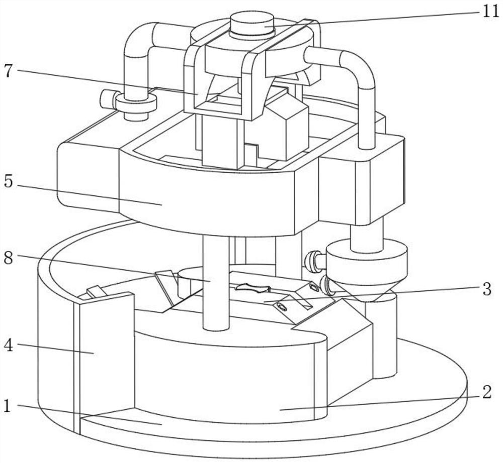
[0036] see Figure 1-Figure 5, the present invention provides a technical solution: a stamping device for mechanical equipment parts, which specifically includes:
[0037] A processing base 1, the processing base 1 has a base body, and a processing table 2 arranged on the top of the processing base 1. The top of the processing table 2 is fixedly connected with a stamping die 3, and the top of the processing base 1 is located on one side of the processing table 2. collection device 4;
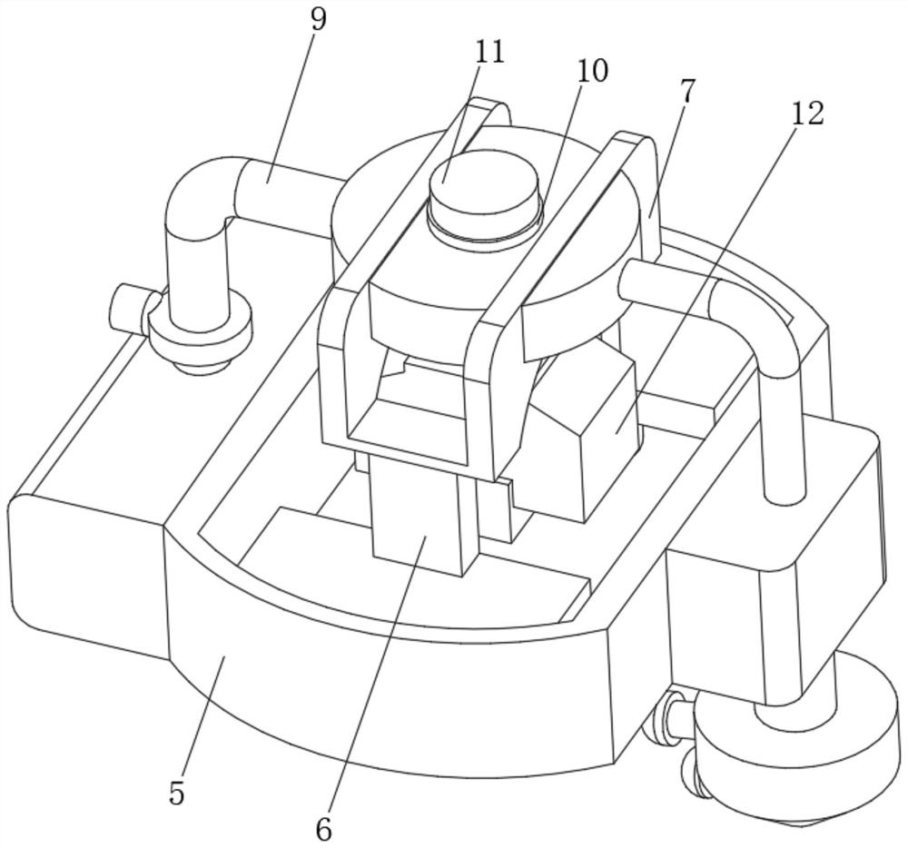
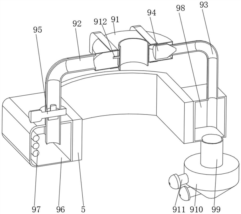
[0038] Fixed bracket 5, the fixed bracket 5 has an arc structure, and a support plate 6 arranged inside the fixed bracket 5, the top of the support plate 6 is fixedly connected with a placement bracket 7, and the bottom of the fixed bracket 5 is connected to the processing table 2 through the connecting column 8 The top of the bracket is fixedly connected, and a heat sink 9 is installed on the outer side of the fixed bracket 5;
[0039] a heat-conducting sleeve 10, the heat-conducting sleeve 1...
Embodiment 2
[0053] see Figure 1-Figure 6 , the present invention provides a technical solution: on the basis of the first embodiment, the collecting device 4 includes an arc-shaped collecting frame 41, and the inside of the arc-shaped collecting frame 41 is fixedly connected with an electromagnet block 42, and the electromagnet block 42 is provided with two groups of , a filter screen 43 is fixedly connected between the two sets of electromagnet blocks 42 .
[0054] The arc-shaped collecting frame 41 is arranged on one side of the processing table 2 and is fixedly connected with the processing base 1 , and the side of the filter screen 43 away from the electromagnet block 42 is fixedly connected with the arc-shaped collecting frame 41 .
[0055] During use, the processed waste is flushed into the arc-shaped collection frame 41 by the water sprayed by the nozzle 911 , the water flows into the bottom of the arc-shaped collection frame 41 through the filter screen 43 , and the waste doped i...
PUM
 Abstract
Description
Claims
Application Information
 - Generate Ideas
- Intellectual Property
- Life Sciences
- Materials
- Tech Scout
- Unparalleled Data Quality
- Higher Quality Content
- 60% Fewer Hallucinations
Browse by: Latest US Patents, China's latest patents, Technical Efficacy Thesaurus, Application Domain, Technology Topic, Popular Technical Reports.
© 2025 PatSnap. All rights reserved.Legal|Privacy policy|Modern Slavery Act Transparency Statement|Sitemap|About US| Contact US: help@patsnap.com