Laminated RGV feeding trolley
A feeding trolley, stacking technology, applied in the directions of transportation, packaging, storage devices, etc., can solve the problems that the shelves cannot convey goods, the trolley deviates from the track, etc., and achieves the effect of facilitating installation, improving efficiency, and improving work efficiency.
- Summary
- Abstract
- Description
- Claims
- Application Information
AI Technical Summary
Problems solved by technology
Method used
Image
Examples
Embodiment 1
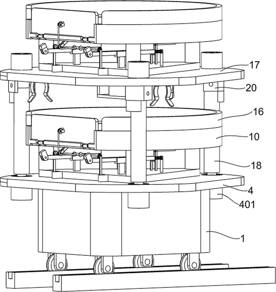
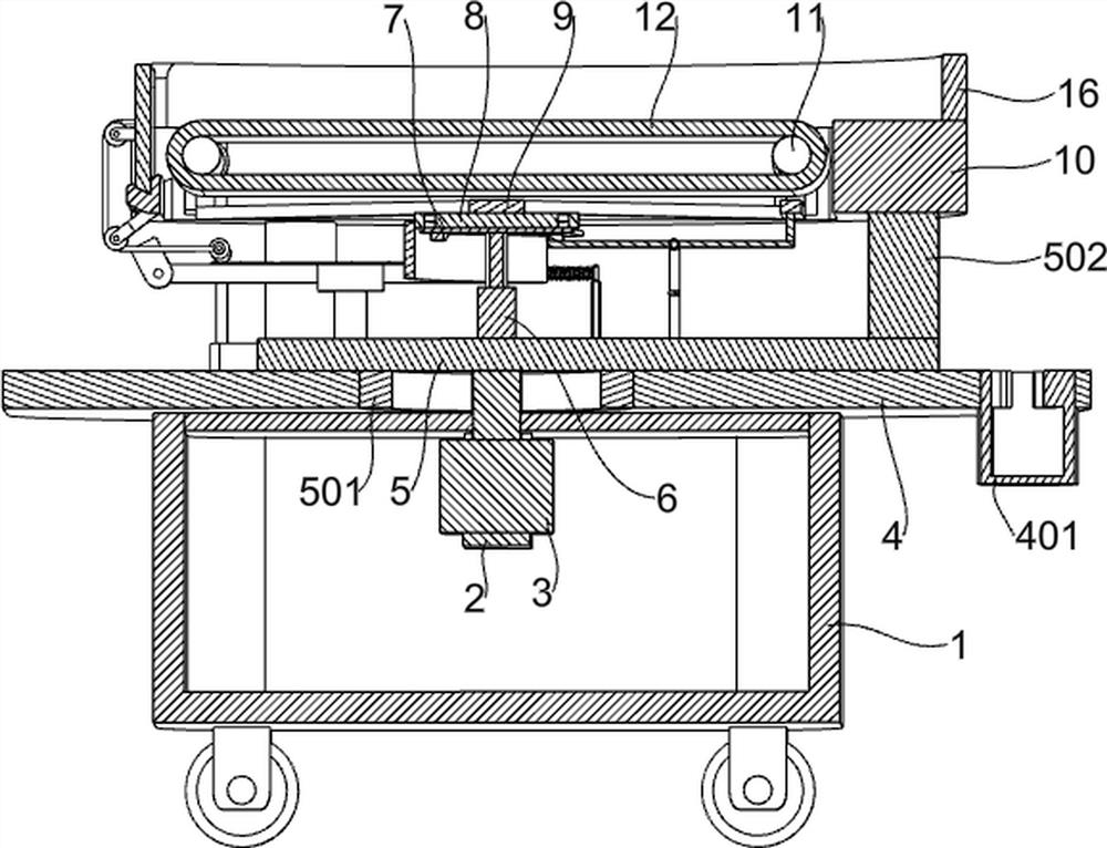
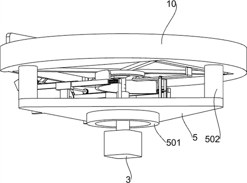
[0041] A stacked RGV feeding trolley, such as figure 1 , figure 2 , image 3 , Figure 4Shown includes RGV trolley 1, first support frame 2, first motor 3, first base 4, first concave clamping column 401, triangular plate 5, bearing 501, support column 502, pallet 10, second base 17 , the second concave clamping column 1701, the electric telescopic rod 18, the convex clamping column 19 and the hinge seat 20, the RGV trolley 1 is fixedly connected with a first support frame 2, and the first support frame 2 is installed with a first motor 3, RGV The upper side of the trolley 1 is fixedly connected with a first base 4, the upper side of the first base 4 is symmetrically and fixedly connected with three first concave clamping columns 401, the upper side of the first base 4 is rotatably connected with a triangular plate 5, and the lower side of the triangular plate 5 is rotatably connected There is a bearing 501, the bearing 501 is rotatably connected with the first base 4, the...
Embodiment 2
[0044] On the basis of Example 1, as Figure 5 , Image 6 , Figure 7 , shown, also includes a conveying mechanism, the conveying mechanism is installed in the pallet 10, the conveying mechanism includes a second support frame 9, a ring 901, a first spring 902, an electric idler 11, an idler 2 1101 and a conveyor belt 12 , the four ends of the second support frame 9 are fixedly connected with a circular ring 901 and a first spring 902, and the circular ring 901 is rotatably connected with an electric roller one 11 and two rollers 1101, and an electric roller one 11 and two rollers 1101 Shangrao With the conveyor belt 12, the other end of the first spring 902 is installed in the pallet 10.
[0045] The middle of the pallet 10 is set in a hollow state, and the conveyor belt 12 and the pallet 10 are in a horizontal state, so the goods will also be on the upper side of the conveyor belt 12. When the pallet 10 rotates, it drives the second support frame 9 and the electric idler 1...
Embodiment 3
[0047] On the basis of Example 1, as Figure 8 , Figure 9 , Figure 10 , Figure 11 As shown, it also includes a lifting mechanism, the second support frame 9 of the conveyor is slidably connected with the pallet 10, the lifting mechanism is arranged below the conveyor, and the lifting mechanism includes a second motor 6, a first disc 7, and a rolling ball 703. , the second disc 8 and the track 801, the second motor 6 is installed on the upper side of the triangular plate 5, the output shaft of the second motor 6 is fixedly connected with the first disc 7, and the upper side of the first disc 7 is symmetrically and fixedly connected with two There are rolling balls 703 , a second disk 8 is rotatably connected to the first disk 7 , a track 801 is arranged in the second disk 8 , and the upper side of the second disk 8 is fixedly connected to the second support frame 9 .
[0048] When conveying the goods, first start the second motor 6, the output shaft of the second motor 6 ...
PUM
 Abstract
Description
Claims
Application Information
 - R&D
- Intellectual Property
- Life Sciences
- Materials
- Tech Scout
- Unparalleled Data Quality
- Higher Quality Content
- 60% Fewer Hallucinations
Browse by: Latest US Patents, China's latest patents, Technical Efficacy Thesaurus, Application Domain, Technology Topic, Popular Technical Reports.
© 2025 PatSnap. All rights reserved.Legal|Privacy policy|Modern Slavery Act Transparency Statement|Sitemap|About US| Contact US: help@patsnap.com


