

Method for judging replacement opportunity of SCR catalyst in case of abrasion
An SCR catalyst and catalyst technology, which is used in the testing of wear resistance and complex mathematical operations to achieve the effects of convenient acquisition, improved accuracy and real-time performance.
Pending Publication Date: 2022-07-15
CENT CHINA BRANCH OF CHINA DATANG CORP SCI & TECH RES INST CO LTD
View PDF0 Cites 0 Cited by
- Summary
- Abstract
- Description
- Claims
- Application Information
AI Technical Summary
Problems solved by technology
[0007] In view of the deficiencies in the prior art, the purpose of the present invention is to provide a method for judging the timing of SCR catalyst wear and replacement, which can effectively solve
Method used
View moreImage
Smart ImageViewing Examples

Examples
 PUM
 Abstract
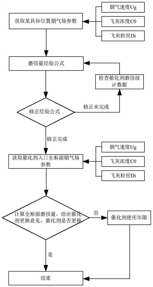
The invention relates to a method for judging the wear replacement time of an SCR (Selective Catalytic Reduction) catalyst, which is characterized in that a constant in a wear loss calculation formula is corrected by comparing a calculated wear loss with an actual wear loss, so that the calculation of the wear loss is more practical, and the measurement accuracy is improved; a database is established based on different load sections, different positions, different time weights and different parameter types, actual wear data after system implementation are accurately predicted through a large amount of measurement data before system implementation, once data acquisition is completed and the system implementation is performed, calculation of wear loss shows a real-time characteristic, and the real-time performance of the system is improved. Compared with a laboratory wear test, the method is closer to the field reality, and compared with a numerical simulation method, the real-time performance can be embodied; after the method is implemented, the abrasion loss is more convenient to obtain and is only related to time and load, and the abrasion condition of any position can be displayed in real time, so that the abrasion parameters of different positions are obtained in real time, and the replacement opportunity of the catalyst is given.
Description
technical field [0001] The invention designs the catalyst wear treatment of the SCR reactor, particularly a method for judging the wear and replacement timing of the SCR catalyst. Background technique [0002] With the implementation of the emission limit of 50mg / m3 of nitrogen oxides in my country's air pollutant emission standards, the denitration system (SCR) has become an essential supporting facility for power station boilers, and the importance of reliable operation of the denitration system has become increasingly prominent. [0003] A 2×660MW ultra-supercritical transformer direct current furnace manufactured by a domestic power plant for Shanghai Boiler Factory is equipped with an SCR denitration system of an environmental protection engineering company in Shanghai. The denitration system was put into use in 2010. In 2011, the catalyst was found to have wear problems. At the beginning of 2013, the furnace was shut down again for inspection, and it was found that the...
Claims
Login to View More Application Information
Patent Timeline
 IPC IPC(8): G01N3/56G06F17/15
CPCG01N3/56G06F17/15
Inventor安敬学罗雪娇赵瑞松绳冉冉杨彬张素丽张天桦虞昊天
OwnerCENT CHINA BRANCH OF CHINA DATANG CORP SCI & TECH RES INST CO LTD