
Telescopic method based on screw telescopic push rod

A screw and push rod technology, applied in electromechanical devices, casings/covers/supports, electrical components, etc., can solve the problems of large occupied space, small occupied space, complicated structure of telescopic push rods, etc., and achieve small occupied space. , high reliability, simple expansion method

Pending Publication Date: 2022-07-15
SHENZHEN UNIV
View PDF0 Cites 0 Cited by
  • Summary
  • Abstract
  • Description
  • Claims
  • Application Information

AI Technical Summary

Problems solved by technology

[0007] The present invention overcomes the complex structure of existing telescopic push rods existing in the above-mentioned prior art, takes up a large space, and is difficult to achieve efficient transmission in a relatively short cabin size, and is not suitable for fidelity transfer of deep in-situ coring. In order to solve the technical problems of position operation, provide a telescopic method that can realize efficient transmission in a relatively short cabin size. The telescopic method is based on a screw telescopic push rod with simple structure, small footprint, and is suitable for deep in-situ extraction. Core-Fidelity Shift Operation

Method used


Image

  • Telescopic method based on screw telescopic push rod
  • Telescopic method based on screw telescopic push rod
  • Telescopic method based on screw telescopic push rod

Examples


Embodiment 1

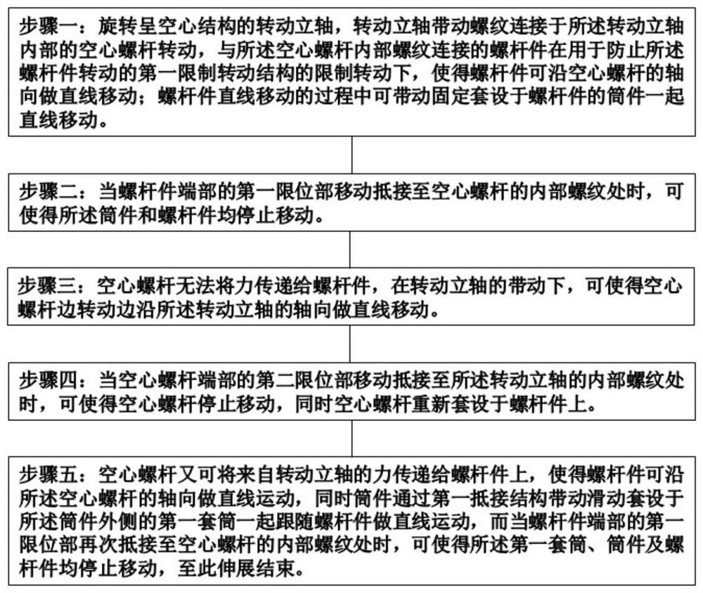
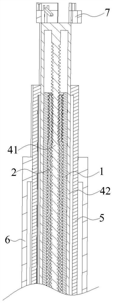
[0056] like Figure 1-Figure 23 Shown is an embodiment of a telescopic method based on a screw telescopic push rod, which specifically includes the following steps:

[0057] Step 1: Rotate the rotating vertical shaft 1 with a hollow structure, the rotating vertical shaft 1 drives the hollow screw 2 threadedly connected to the inside of the rotating vertical shaft 1 to rotate, and the screw member 41 threadedly connected with the hollow screw 2 is used to prevent the Under the restricted rotation of the first rotation-restricting structure for the rotation of the screw member 41, the screw member 41 can move linearly along the axial direction of the hollow screw 2; during the linear movement of the screw member 41, it can drive the cylinder fixedly sleeved on the screw member 41. Pieces 42 move linearly together;

[0058] Step 2: When the first limiting portion 411 at the end of the screw member 41 moves and abuts against the inner thread of the hollow screw 2, the cylinder me...

Embodiment 2

[0086] This embodiment is Embodiment 2 of a telescopic method based on a screw telescopic push rod. The screw telescopic push rod used in this embodiment is different from the screw telescopic push rod used in Embodiment 1 in that: this embodiment Zhongru Figure 20 As shown, one end of the second sleeve 6 is detachably connected with an end cover 62. In this embodiment, the end cover 62 is screwed on the second sleeve 6, and the end cover 62 is movably sleeved on the gear shaft 13, so that it is convenient to thread The disassembly and assembly of the telescopic push rod is very convenient to use.

Embodiment 3

[0088] This embodiment is Embodiment 3 of a telescopic method based on a screw telescopic push rod. The screw telescopic push rod used in this embodiment is different from the screw telescopic push rod used in Embodiment 2 in that: this embodiment The outer wall of the first limit ring 43 is provided with a first protruding strip 81 along the axial direction of the first limit ring 43 , and the inner wall of the first sleeve 5 is provided with a second limit along the axial direction of the first sleeve 5 . The grooves 82 and the first protruding strips 81 are inserted into the first grooves 82 , which can further improve the stability of the movement of the cylindrical member 42 in the first sleeve 5 . A plurality of first protruding strips 81 are provided, and a plurality of first protruding strips 81 are evenly distributed on the first limiting ring 43 along the circumferential direction of the first limiting ring 43 , wherein several first grooves 82 are provided, A plural...


PUM


Abstract

The invention relates to the technical field of rock mass in-situ mechanical research, in particular to a telescopic method based on a screw telescopic push rod, which comprises the following specific steps: rotating a rotating vertical shaft, and driving a screw piece to do linear motion along the axial direction of a hollow screw by the rotating vertical shaft through the hollow screw; when a first limiting part on the screw rod piece moves to an internal thread of the hollow screw rod, the first limiting part stops moving, the hollow screw rod linearly extends outwards, when a second limiting part of the hollow screw rod moves to an internal thread of the rotating vertical shaft, the second limiting part stops moving, and finally the screw rod piece and the barrel piece drive the first sleeve to linearly move outwards together. And when the first limiting part on the screw rod piece moves to the internal thread of the hollow screw rod again, the movement is stopped, so that the extension is finished. The device is simple and easy to operate, is different from a telescopic mode of an existing conventional telescopic push rod structure, is high in transmission efficiency and short in transmission time, can realize large-distance transmission in a relatively short cabin body size, and is suitable for fidelity displacement operation of deep in-situ coring.

Description

technical field [0001] The invention relates to the technical field of rock mass in-situ mechanics research, and more particularly, to a telescopic method based on a screw telescopic push rod. Background technique [0002] In order to implement the requirements for resource exploration and reserve increase proposed in the Outline of the National Medium- and Long-Term Science and Technology Development Plan (2006-2020) and the relevant deployments such as the Outline of Strategic Action for Prospecting Breakthroughs (2011-2020), and based on major national Funded projects "Reconstruction of deep in-situ environment and displacement of cores" and the national key R&D program "Deep rock mass mechanics and mining theory" propose that in-situ environments (such as stress, temperature, humidity, composition, etc.) exist in the deep earth. etc.) and in-situ fidelity coring, fidelity displacement and fidelity testing of deep rocks in a deep in situ engineering disturbance environmen...

Claims


Application Information

Patent Timeline
Patent Type & Authority Applications(China)
IPC IPC(8): H02K7/06H02K5/16
CPCH02K7/06H02K5/163
Inventor 彭小波宋霖毛彦毫
Owner SHENZHEN UNIV
Learn More