Device for fixing circuit

A technology for fixing lines and fixing parts, applied in the field of pipes or hoses, and cables, it can solve the problems of difficult assembly, high number of components, etc., and achieve the effect of simple calibration, ensuring holding force, and uniform force transmission.

Pending Publication Date: 2022-07-15
WALTER STAUFFENBERG
View PDF0 Cites 0 Cited by
  • Summary
  • Abstract
  • Description
  • Claims
  • Application Information

AI Technical Summary

Problems solved by technology

A disadvantage of these clips is that they entail a relatively high component count, which makes assembly difficult

Method used


Image

  • Device for fixing circuit
  • Device for fixing circuit
  • Device for fixing circuit

Examples


Embodiment Construction

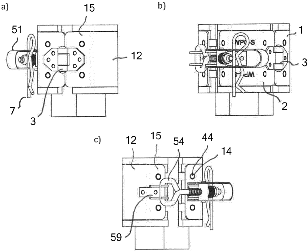
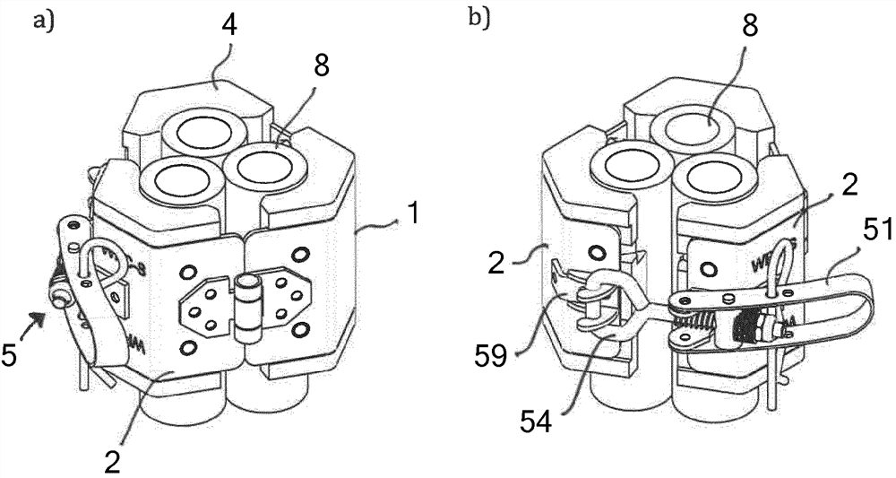
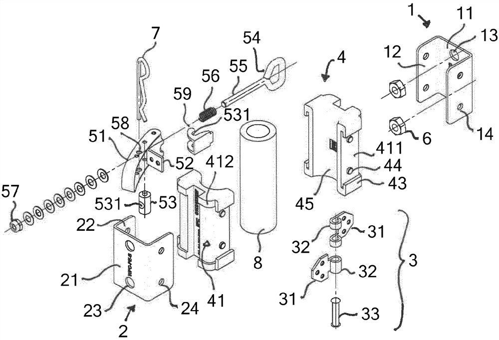
[0035] The device chosen as an example for fixing lines, in particular electrical lines, in a tower of a wind power installation comprises a first clip part 1 and a second clip part 2 which are connected to each other in an articulated manner via a hinge 3 and which The clamping blocks 4 are each accommodated, wherein a tensioning closure 5 is arranged, via which the two clamping parts 1 , 2 can be tensioned relative to each other.

[0036] on the basis of figure 1 In the exemplary embodiment of the present invention, the two clip parts 1 , 2 are embodied as identical C-shaped sheet metal bent parts and have end sides 11 , 21 , on whose longitudinal sides two oppositely arranged lateral wings 12 , 22 are molded. The flanks 12 , 22 are placed at right angles to the end sides 11 , 21 at these end sides. In the middle, two bores 13 , 23 are introduced into the end sides 11 , 21 at a distance from each other. In alignment with the holes 13 , 23 , to the end sides 11 , 21 , on th...


PUM


Abstract

The invention relates to a device for fastening a line (8), in particular a cable, a pipeline or a hose, comprising at least two fastening parts which can be connected to each other and which form a feed-through in the assembled state, the fastening parts comprising two clamping parts (1, 2) which are connected to each other in an articulated manner via at least one hinge (3), the clamping elements (1, 2) each receive at least one clamping block (4), which has a groove (41) on the outer circumferential surface thereof, in which groove a section of the clamping element (1, 2) is positioned, and which, on the inner side thereof opposite the groove (41), has a groove (43) in the form of a cylindrical cover section, which groove runs axially at right angles to the groove (41), for receiving a line, and wherein the clamping elements (1, 2) are arranged in the groove (41). A tensioning closure (5) is arranged at the end of the clip part (2) opposite the hinged connection, the tensioning hook (54) of which can engage with a counter hook arranged at the end of the other clip part (1) opposite the hinged connection.

Description

technical field [0001] The present invention relates to a device for securing lines, in particular cables, pipes or hoses, according to the preamble of patent claim 1 . Background technique [0002] In order to fasten lines, in particular cables, pipes and hoses, so-called clips (Schelle, sometimes also called clips) are often used, which clips comprise clip bodies made of thermoplastic or elastomer plastic or Even made of metal. The clip body is often formed from two fastening parts which can be connected to one another by means of screws, which in the assembled state form lead-throughs for accommodating lines. [0003] For laying and securing cables and lines in the towers of wind installations (Windkraftanlage, also sometimes referred to as wind turbines), various designs of clips of the type described above are currently used. The disadvantage of these clips is that they entail a high number of components, which makes assembly difficult. SUMMARY OF THE INVENTION [...

Claims


Application Information

Patent Timeline
Patent Type & Authority Applications(China)
IPC IPC(8): F16L3/10F16L3/23H02G3/32F03D80/80F16B2/10F16B2/18F16B7/04
CPCF16L3/1075F16L3/23F16L3/1025H02G3/32F16B7/0433F16B2/10F16B2/185F03D80/85Y02E10/72
Inventor U·S·克尼格M·舒尔茨
Owner WALTER STAUFFENBERG
Why Eureka
Try Eureka