Molding method
A technology of forming processing and heating process, applied in the direction of forming tools, metal processing equipment, manufacturing tools, etc., can solve the problem of expanding the heating range and achieve the effect of stable current value
- Summary
- Abstract
- Description
- Claims
- Application Information
AI Technical Summary
Problems solved by technology
Method used
Image
Examples
Embodiment approach 1
[0041] Hereinafter, the present invention will be described based on the embodiments of the invention, but the technical aspects of the claims are not limited to the following embodiments. In addition, all the configurations described in the embodiments are not necessarily essential as means for solving the problems.
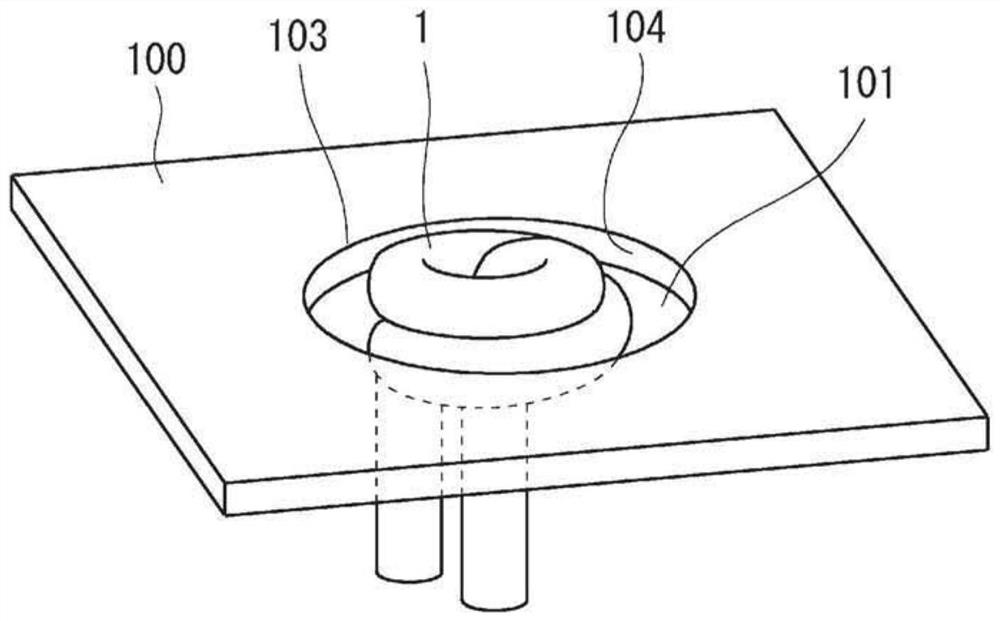
[0042] figure 1 It is a schematic diagram which shows roughly the process of the shaping|molding processing method of this embodiment. The forming method described below is a method of forming a flange 102 by providing a perforation 101 in a steel sheet 100 as a workpiece, and deforming the peripheral edge of the perforation 101 .
[0043] like figure 1 As shown, the forming method of the present embodiment includes, for example: a blanking step of blanking the steel sheet 100; a heating step of heating the blanked end 103; a natural cooling step of cooling the heat generated by the heating step; and forming the blanked end 103 The stretch flange forming proc...
Embodiment approach 2
[0082] In the second embodiment, the steel sheet formed product punched out in the above-mentioned punching step is placed in a heating jig in the heating step, and heated. Figure 17 It is a figure which shows an example of a heating jig. Figure 17 The figure on the left shows the state before the formed steel sheet X is arranged on the heating jig 400 , and the figure on the right shows the state after the formed steel product X is arranged on the heating jig 400 .
[0083] like Figure 17 As shown, the heating jig 400 includes a heating coil 1 for heating the punched end 103 of the steel sheet formed product X, a positioning guide 2 for positioning the steel sheet formed product X at a predetermined position, and a base portion 3 . An AC power source 4 for supplying electric power to each heating coil 1 is connected to each heating coil 1 .
[0084] The shape and arrangement of the positioning guides 2 are set so that the position of the steel sheet formed product X is n...
PUM
| Property | Measurement | Unit |
|---|---|---|
| tensile strength | aaaaa | aaaaa |
| Vickers hardness | aaaaa | aaaaa |
Abstract
Description
Claims
Application Information
 - R&D
- Intellectual Property
- Life Sciences
- Materials
- Tech Scout
- Unparalleled Data Quality
- Higher Quality Content
- 60% Fewer Hallucinations
Browse by: Latest US Patents, China's latest patents, Technical Efficacy Thesaurus, Application Domain, Technology Topic, Popular Technical Reports.
© 2025 PatSnap. All rights reserved.Legal|Privacy policy|Modern Slavery Act Transparency Statement|Sitemap|About US| Contact US: help@patsnap.com


