Battery charging control method, storage medium and electronic equipment

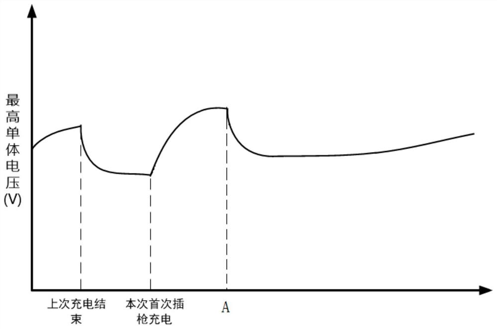
A battery charging and control method technology, applied in battery/fuel cell control devices, electric vehicle charging technology, charging stations, etc., can solve the problem that the charging current can only be reduced, the charging current fluctuates greatly, and quickly climbs to point A, etc. problem, to achieve the effect of stabilizing charging current, improving charging efficiency, and avoiding fluctuations

Active Publication Date: 2021-04-16
DONGFENG MOTOR CO LTD
View PDF11 Cites 0 Cited by
  • Summary
  • Abstract
  • Description
  • Claims
  • Application Information

AI Technical Summary

Problems solved by technology

figure 1 It shows the schematic diagram of the voltage change of the battery cell when the lithium battery is charged with a plug gun at the end of charging, that is, when the remaining capacity of the battery is high. The cell voltage when the gun is charging is actually lower than the cell voltage after the last charge, so the charging current after the gun is inserted is larger
The larger charging current will bring about the battery polarization voltage, which will cause the cell voltage to rise rapidly to point A. At this time, look up the table again, and the charging current will be greatly reduced. Under the same temperature, the cell voltage will tend to a stable voltage value lower than the cell voltage at point A, and since the charging current can only decrease but not increase at the same temperature, it can only be charged with a small charging current.
[0003] It can be seen that in the existing charging strategy, the lithium battery is charged when the remaining capacity of the battery is high, and the charging current fluctuates greatly in a short period of time, which is easy to accelerate the aging of the battery, and the charging current will eventually stabilize at a lower value. prolong charging time

Method used


Image

  • Battery charging control method, storage medium and electronic equipment
  • Battery charging control method, storage medium and electronic equipment
  • Battery charging control method, storage medium and electronic equipment

Examples


Embodiment Construction

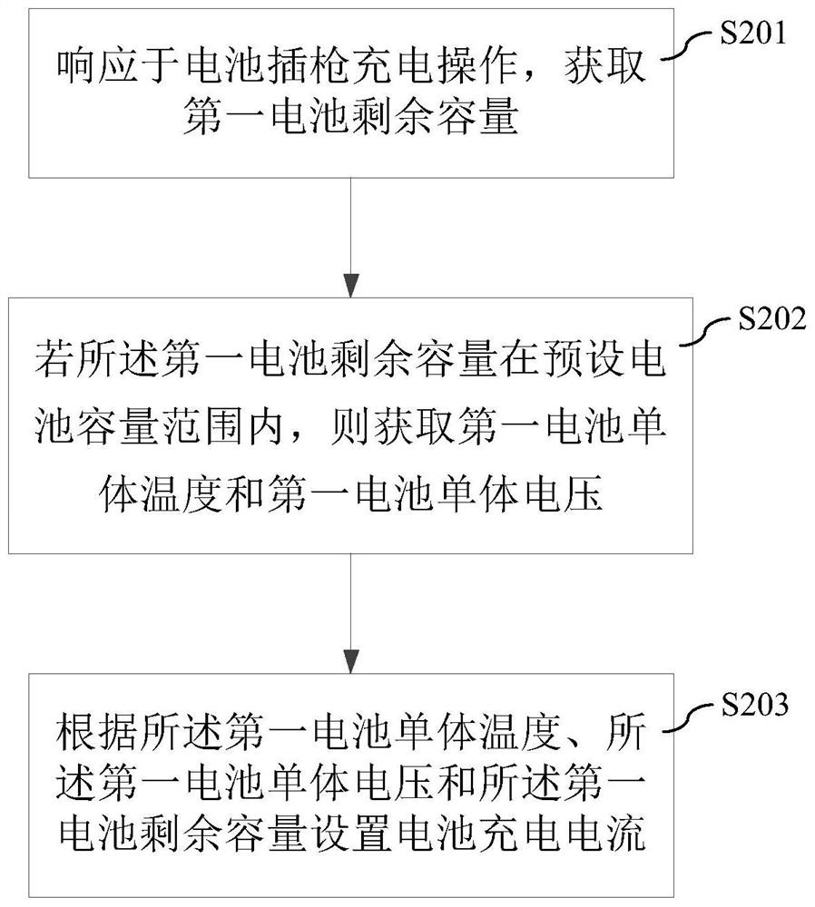
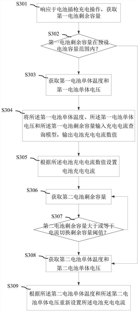
[0057] The specific implementation manner of the present application will be further described below in conjunction with the accompanying drawings.

[0058] It is easy to understand that, according to the technical solutions of the present application, those skilled in the art may replace various structural modes and implementation modes without changing the spirit of the present application. Therefore, the following specific embodiments and drawings are only exemplary descriptions of the technical solution of the application, and should not be regarded as the entirety of the application or as a limitation or restriction on the technical solution of the application.

[0059]The directional terms such as up, down, left, right, front, back, front, back, top, and bottom that are mentioned or may be mentioned in this specification are defined relative to the structures shown in the drawings, and they are It is a relative concept, so it may change accordingly according to its diffe...


PUM


Abstract

The invention discloses a battery charging control method, a storage medium and electronic equipment, and the method comprises the steps: obtaining the residual capacity of a first battery in response to a battery gun insertion charging operation; if the residual capacity of the first battery is within a preset battery capacity range, acquiring a first battery monomer temperature and a first battery monomer voltage; and setting a battery charging current according to the first battery monomer temperature, the first battery monomer voltage and the first battery residual capacity. When the battery is inserted into a gun for charging, the first battery residual capacity is obtained firstly, whether the battery is in the later charging period or not is judged, if yes, the battery charging current is set according to the temperature of the single battery, the voltage of the single battery and the battery residual capacity, and due to the fact that the battery residual capacity cannot be depolarized or fluctuated due to change of the charging current, stable charging current can be provided, charging current fluctuation is avoided, the charging current can be kept at a stable current value, and the charging efficiency is improved.

Description

technical field [0001] The present application relates to the technical field of automobile batteries, in particular to a battery charging control method, a storage medium and electronic equipment. Background technique [0002] The existing charging strategy for automotive lithium batteries is to query the charging current with the cell voltage and temperature and the two-dimensional table. At the same temperature, the lower the cell voltage, the greater the queried charging current. figure 1 It shows the schematic diagram of the voltage change of the battery cell when the lithium battery is charged with a plug gun at the end of charging, that is, when the remaining capacity of the battery is high. The cell voltage when the gun is charging is actually lower than the cell voltage after the last charge, so the charging current after the gun is inserted is relatively large. The larger charging current will bring about the battery polarization voltage, which will cause the cell...

Claims


Application Information

Patent Timeline
Patent Type & Authority Applications(China)
IPC IPC(8): B60L58/12B60L58/10B60L53/00
CPCY02T10/70Y02T10/7072Y02T90/14
Inventor 周万阳卜健曾亮铭王君
Owner DONGFENG MOTOR CO LTD
Why Eureka
Try Eureka