[0036] Example: please refer to Figure 1 to Figure 8 :
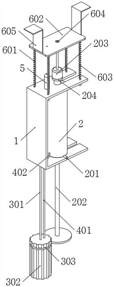
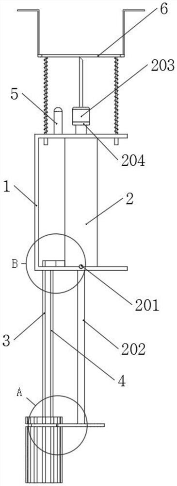
[0037] The present invention proposes an anesthesia puncture needle structure, comprising: a base body 1, a syringe tube 2, a propelling part 3, a marking part 4 and a cleaning part 6;
[0038] The seat body 1 is a concave structure, and the syringe barrel 2 is installed in the seat body 1, and the laser detector 5 is installed on the seat body 1;
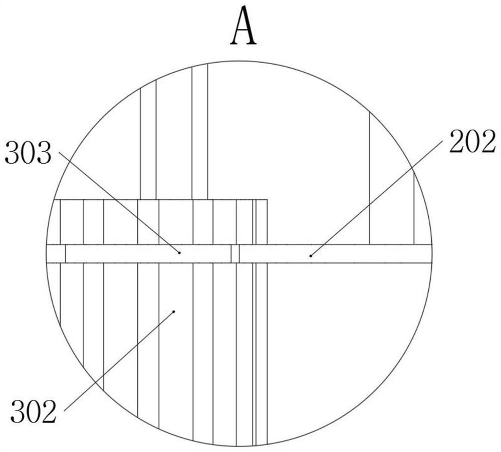
[0039] The advancing part 3 is composed of a threaded rod 301, a handle B302 and a clamping slot B303, and the threaded rod 301 is threadedly connected to the seat body 1;
[0040] The marking part 4 consists of a sliding rod A401 and a cutter 402, and the sliding rod A401 is slidably connected to the base body 1;
[0041] The cleaning part 6 is composed of a sliding rod B601, a protective plate 602, an elastic member 603, a cleaning cotton 604, a through hole 605 and a support arm 606, and there are four sliding rods B601 in total, and the four sliding rods B601 are all slidably connected to the seat body 1 on.
[0042] Furthermore, according to embodiments of the present invention, as Figure 8 As shown, two card slots A101 are symmetrically opened on the base body 1, and the two card slots A101 are both semi-cylindrical groove structures;
[0043] Two handles A201 are symmetrically welded on the syringe barrel 2, and the two handles A201 are both cylindrical rod-shaped structures, and the two handles A201 are respectively connected with the two clamping slots A101, so that the clamping connection of the syringe barrel 2 can be realized. atresia.
[0044] Furthermore, according to embodiments of the present invention, as Figure 8 As shown, a piston rod 202 is slidably connected in the syringe tube 2, and a needle 203 is installed on the syringe tube 2;
[0045] A stopper 204 is welded on the syringe barrel 2 . When the needle 203 is installed, the needle 203 contacts with the stopper 204 , thereby improving the sealing performance between the needle 203 and the stopper 204 .
[0046] Furthermore, according to embodiments of the present invention, as figure 1 As shown, the handle B302 is welded on the threaded rod 301, and the handle B302 is provided with a slot B303; the slot B303 is an annular groove structure, and when the handle A201 and the slot A101 are engaged, the tail end of the piston rod 202 and the slot The B303 is in a snap-on state, and at this time, the threaded rod 301 can be rotated to achieve injection, and the injection accuracy is higher.
[0047] Furthermore, according to embodiments of the present invention, as Figure 4 As shown, a cutter 402 is installed on the sliding rod A401, and the cutter 402 is in contact with the threaded rod 301, and the threaded rod 301 constitutes an axial limit structure of the cutter 402, thereby preventing the cutter 402 from rotating axially.
[0048] Furthermore, according to embodiments of the present invention, as figure 2 and Figure 4 As shown in the figure, the bottom end surface of the sliding rod A401 is in contact with the top end surface of the handle B302, and when the handle A201 is clamped with the slot A101, the cutter 402 is in contact with the syringe barrel 2, and the syringe barrel 2 is made of plastic material, so that when the handle B302 is rotated, it passes through The extrusion of the handle B302 can realize the upward movement of the sliding rod A401 and the cutter 402, thereby completing the scratching of the syringe barrel 2, and finally realizing the marking of the syringe barrel 2 after use.
[0049] Furthermore, according to embodiments of the present invention, such as figure 1 As shown, the head ends of the four sliding rods B601 are installed with a protective plate 602, and the four sliding rods B601 are all stepped shaft structures; each sliding rod B601 is sleeved with an elastic member 603, and the four elastic members are 603 together constitute the elastic stretching structure of the protective plate 602, and the protective plate 602 is located above the needle head 203 under the elastic force of the four elastic pieces 603, so that the needle head 203 can be protected.
[0050] Furthermore, according to embodiments of the present invention, such as Figure 5 and Image 6 As shown, a cleaning cotton 604 is installed in the protective plate 602, and the cleaning cotton 604 is aligned with the needle head 203, and the cleaning cotton 604 constitutes the wiping and cleaning structure of the needle head 203, so that when the protective plate 602 shrinks, the cleaning cotton 604 can realize Wipe cleaning of needle 203.
[0051] Furthermore, according to embodiments of the present invention, such as Image 6 As shown, a through hole 605 is opened on the protective plate 602, and the through hole 605 is a cylindrical hole-like structure; the through hole 605 is aligned with the laser detector 5, and when the protective plate 602 is elastically reset, the through hole 605 is a jet flow state, and the through hole 605 constitutes the air flow cleaning structure of the laser detector 5, so that the dust on the laser detector 5 can be cleaned by the jet.
[0052] Furthermore, according to embodiments of the present invention, such as figure 1 As shown, two supporting arms 606 are symmetrically welded on the protective plate 602, and the two supporting arms 606 are both L-shaped plate structures; the two supporting arms 606 and the protective plate 602 together form a "concave" fixed structure, and The "concave"-shaped fixing structure is fastened and fixed at the patient's wrist, so as to prevent the needle 203 from being damaged due to the resistance caused by the patient's tension during injection.
[0053] The specific usage mode and function of this embodiment:
[0054] During assembly, the syringe tube 2 is fixed in the base body 1. At this time, two clamping slots A101 are symmetrically opened on the base body 1, and the two clamping slots A101 are semi-cylindrical groove-shaped structures; Two handles A201 are symmetrically welded, and the two handles A201 are both cylindrical rod-shaped structures, and the two handles A201 are respectively connected with the two card slots A101, so that the locking and locking of the syringe barrel 2 can be realized;
[0055] The support arm 606 is clamped to the patient's wrist, and then the handle B302 is rotated to realize the injection. At this time, because the protective plate 602 is provided with a through hole 605, and the through hole 605 is a cylindrical hole-shaped structure; the through hole 605 is connected with the laser detection The position of the detector 5 is aligned, and when the protective plate 602 is elastically reset, the through hole 605 is in a jet state, and the through hole 605 constitutes the airflow cleaning structure of the laser detector 5, so that the dust on the laser detector 5 can be cleaned by the jet. Because two supporting arms 606 are symmetrically welded on the protective plate 602, and the two supporting arms 606 are both L-shaped plate structures; the two supporting arms 606 and the protective plate 602 jointly form a "concave" fixed structure, and the The "concave"-shaped fixing structure is fastened and fixed at the patient's wrist, so as to prevent the needle 203 from being damaged due to the resistance caused by the patient's tension during injection;
[0056] At the same time, because the handle B302 is welded on the threaded rod 301, and the handle B302 is provided with a slot B303; the slot B303 is an annular groove structure, and when the handle A201 and the slot A101 are clamped, the tail end of the piston rod 202 is connected to the The card slot B303 is in the carded state, then at this time, the threaded rotation of the threaded rod 301 can realize injection, and the injection accuracy is higher;
[0057] At the same time, because the bottom end surface of the sliding rod A401 is in contact with the top end surface of the handle B302, and when the handle A201 is clamped with the slot A101, the cutter 402 is in contact with the syringe tube 2, and the syringe tube 2 is made of plastic material, so when the handle B302 rotates At the same time, the upward movement of the sliding rod A401 and the cutter 402 can be realized by pressing the handle B302, thereby completing the scratching of the syringe barrel 2, and finally realizing the marking of the syringe barrel 2 after use.