
Oil return method for shaft seat lubricated by circulating oil

A technology of circulating oil and lubricating oil, applied in forming tools, metal processing equipment, manufacturing tools, etc., can solve the problems of insufficient lubrication of parts and components, and achieve sufficient and reliable lubrication and good fluidity

Pending Publication Date: 2022-07-22
XIE YI TECH MACHINERY CHINA
View PDF7 Cites 0 Cited by
  • Summary
  • Abstract
  • Description
  • Claims
  • Application Information

AI Technical Summary

Problems solved by technology

[0005] 2. Insufficient lubrication of parts caused by high-speed and long-stroke deep drawing process

Method used


Image

  • Oil return method for shaft seat lubricated by circulating oil
  • Oil return method for shaft seat lubricated by circulating oil
  • Oil return method for shaft seat lubricated by circulating oil

Examples


Embodiment Construction

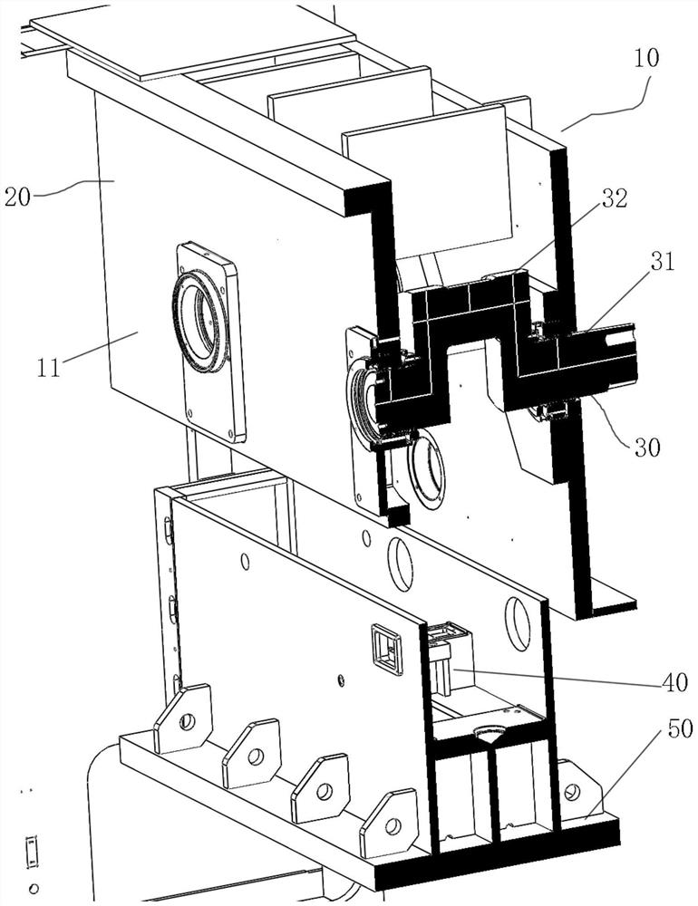
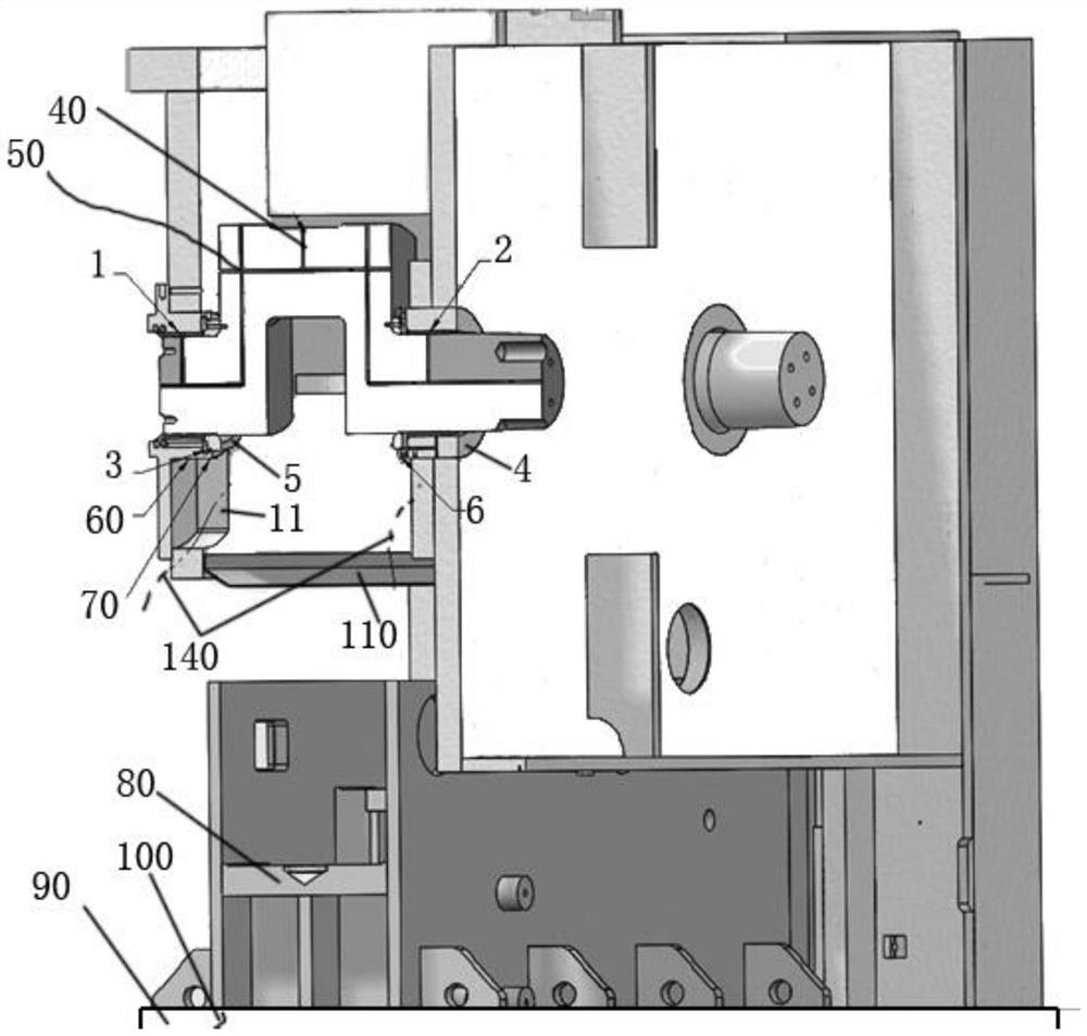
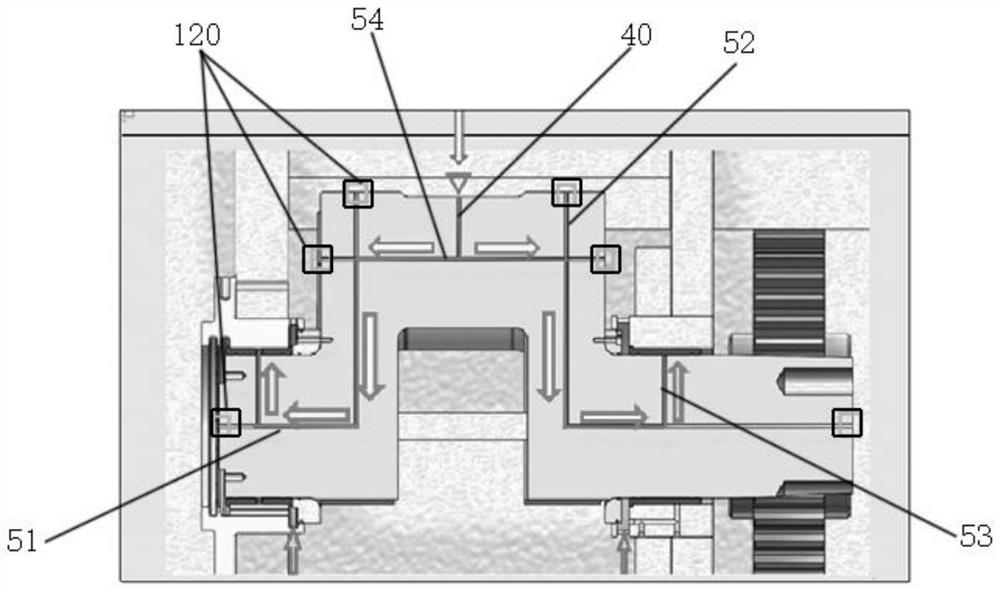
[0022] A method of returning oil to the shaft seat with circulating oil lubrication, see Figure 1-Figure 3 : it includes a frame 10, a crankcase 20, an oil tank (not shown in the figure), the frame 10 is provided with an oil tank corresponding to the lower position of the crankcase 20, and at least one crankshaft 30 is arranged in the crankcase 20, The two shaft ends of the crankshaft 30 are respectively mounted on the mounting and positioning holes of the corresponding frame side plates 11 through the corresponding copper bushings and bushing mounts, and the main body 31 of the crankshaft 30 is provided with an oil inlet hole groove 40 and a guide oil hole groove 50 , the oil tank injects high-pressure thin oil into the oil inlet groove 40 through the oil pump, and the thin oil flows along the oil inlet groove 40 and the guide oil hole groove 50 into the inner and outer ring surfaces of the copper bushing, so that the lubricating oil completes the copper bushing. At the same...


PUM


Abstract

The invention provides an oil return method for a shaft seat lubricated by circulating oil, which ensures that a copper bush correspondingly assembled on a crankshaft is fully and reliably lubricated, and oil liquid for fully lubricating the copper bush is recycled again. The crankshaft structure comprises a rack, a crankshaft box body and an oil tank, the oil tank is arranged at the position, corresponding to the lower portion of the crankshaft box body, of the rack, at least one crankshaft is arranged in the crankshaft box body, and the two shaft ends of the crankshaft are installed in installation positioning holes of corresponding rack side plates through corresponding copper bushes and bush installation bases respectively. The crankshaft is characterized in that the body of the crankshaft is provided with the oil inlet groove and the guide oil hole groove, the oil tank injects high-pressure thin oil into the oil inlet groove through the oil pump, the thin oil flows into the inner ring face and the outer ring face of the copper bush along the oil inlet groove and the guide oil hole groove, and therefore lubricating oil can fully lubricate the copper bush. And meanwhile, an inner groove is formed in the bushing mounting seat, and a transition groove communicated with the inner groove is formed in the position corresponding to the rack side plate.

Description

technical field [0001] The invention relates to the technical field of the oil return of the shaft seat of a punching machine, in particular to an oil return method of the shaft seat lubricated by circulating oil. Background technique [0002] The existing traditional half-door type punch, the front and rear copper bushings of the crankshaft are all intermittent grease lubrication (0# backlog oil), the lubrication efficiency is low, when the SPM speed is too fast and the stroke is too long, it is easy to cause copper bushings Due to insufficient lubrication, there are problems of burning and biting, and the grease from the copper bushing can hardly be recovered for secondary recycling. [0003] Based on the current development of the new energy vehicle industry, more and more stamping and forming industries are transforming into the production of new energy battery casings, and punches with longer strokes and faster speeds are in demand. However, for punch production equipme...

Claims


Application Information

Patent Timeline
Patent Type & Authority Applications(China)
IPC IPC(8): B30B15/00B21D37/18
CPCB30B15/0088B21D37/18
Inventor 郭雅慧郭挺鈞林明暘李威林成龙
Owner XIE YI TECH MACHINERY CHINA
Learn More