Check patentability & draft patents in minutes with Patsnap Eureka AI!

Bicycle pedal force testing device and method thereof

A technology for bicycles and pedals, which is applied in the field of pedal force detection devices, and can solve problems such as the inability to correctly obtain the phase difference of rotating bodies, the increased structural accuracy and assembly workload of two rotating bodies, and the large initial phase offset.

Inactive Publication Date: 2004-04-28
HONDA MOTOR CO LTD
View PDF1 Cites 0 Cited by
  • Summary
  • Abstract
  • Description
  • Claims
  • Application Information

AI Technical Summary

Problems solved by technology

[0004] However, in the above-mentioned human driving torque detection mechanism, when the centers of the above-mentioned pair of rotating bodies deviate, the human driving torque cannot be detected correctly.
In addition, in the assembly stage of the above-mentioned pair of rotating bodies, if the initial phase shift in the direction of rotation is large, then when the human force moment is large, there will be a deviation of more than one cycle of the pulse cycle generated by the sensor, and the error cannot be accurately calculated. Phase difference of a pair of rotating bodies
For this reason, the assembly accuracy of the pair of rotating bodies is required to be high, and the structural accuracy and assembly workload of the two rotating bodies increase, which becomes the reason for increasing the cost.

Method used


Image

  • Bicycle pedal force testing device and method thereof
  • Bicycle pedal force testing device and method thereof
  • Bicycle pedal force testing device and method thereof

Examples


Embodiment Construction

[0035] Embodiments of the present invention will be described below with reference to the drawings.

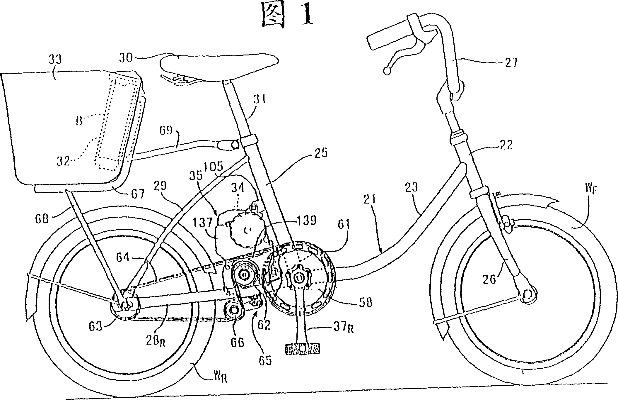
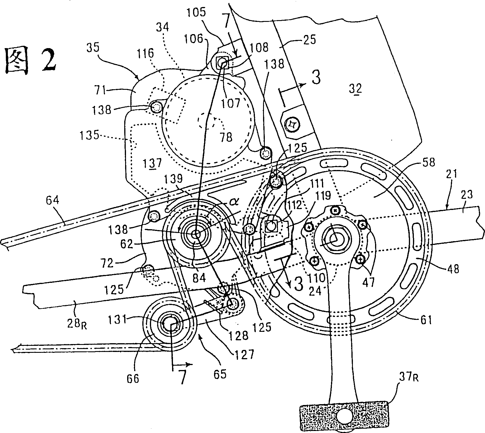
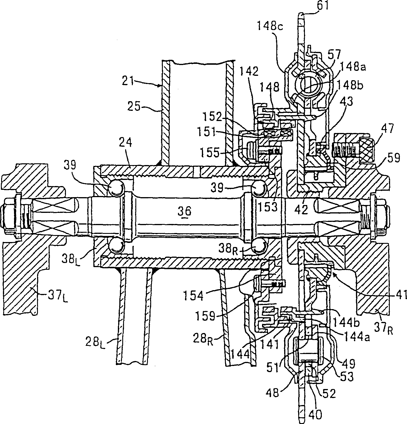
[0036] 1 to 14 show a first embodiment of the present invention applied to a bicycle with an electric motor. Fig. 1 is a side view of a bicycle with an electric motor. FIG. 2 is an enlarged view of an essential part of FIG. 1 . image 3 It is a cross-sectional view taken along line 3-3 in FIG. 2 . Figure 4 yes image 3 The enlarged view of the main part. Figure 5 yes Figure 4 5-5 line sectional view. Figure 6 yes Figure 4 The 6-6 line sectional view. Figure 7 It is a sectional view taken along line 7-7 in FIG. 2 . Figure 8 yes Figure 4 The 8-8 line sectional view. Figure 9 yes Figure 4 The 9-9 line section view. FIG. 10 is a diagram showing the relative arrangement of the first sensor and the magnetic poles of the first magnetic ring. Figure 11 It is a figure explaining the detection pattern of the 1st sensor accompanying the change of the circumferential...


PUM


Abstract

In a pedaling force detecting device for a bicycle for transmitting the force applied to a pedal to a sprocket through an elastic member, two pairs of sensors (151a,152a), (151a',152a') for detecting the magnetism of a first and a second magnetic rings 141, 142 arranged with N-poles and S-poles at equal spaces alternately, which are respectively fixed to the pedal side member and the sprocket are placed at positions apart from each other by about 180 DEG by each one pair, and the phase difference between both magnetic rings 141, 142 is determined by equalizing phase difference obtained by the respective paired sensors. Thus, even if both magnetic rings 141, 142 are axially shifted, the phase difference between both magnetic rings 141, 142 can be accurately determined and the pedaling force can be accurately detected.

Description

technical field [0001] The present invention relates to a bicycle pedaling force detection device and method, in which even if the center deviation of a pair of rotating bodies for detecting pedaling force is deviated, or when a pair of rotating bodies for detecting pedaling force are assembled, even if the initial phase is in the direction of rotation Even if there is a large deviation, the pedaling force can be detected correctly. Background technique [0002] There are various inventions related to bicycles with electric motors in the prior art, and Japanese Patent Application Laid-Open No. 9-290795 is an example thereof. In this invention, the manual drive system and the electric drive system are arranged side by side, and the output of the electric drive system is controlled corresponding to the change of the manual drive system. In this way, the change of the driving force of the motor when the manual drive torque changes sharply is slowed down, and the change of the d...

Claims


Application Information

Patent Timeline
Patent Type & Authority Patents(China)
IPC IPC(8): B62M6/45B62M6/50B62M6/70
CPCB62M6/70B62M6/50B62M6/45
Inventor 本田聪三浦信夫三浦静止
Owner HONDA MOTOR CO LTD
Features
  • R&D
  • Intellectual Property
  • Life Sciences
  • Materials
  • Tech Scout
  • Unparalleled Data Quality
  • Higher Quality Content
  • 60% Fewer Hallucinations
Learn More