Embedded high-strength aluminum profile for rail transit
A rail transit, high-strength technology, applied in the field of aluminum profiles, can solve problems such as reducing the strength of aluminum profiles, and achieve the effects of ensuring load-bearing strength, increasing height, and facilitating access
- Summary
- Abstract
- Description
- Claims
- Application Information
AI Technical Summary
Problems solved by technology
Method used
Image
Examples
Embodiment 1
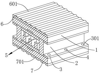
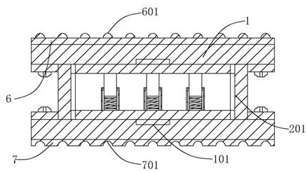
[0022] see Figure 1-4 , the present invention provides a technical solution: an embedded high-strength aluminum profile for rail transit, comprising a profile plate 1,
[0023] see figure 1 and figure 2 , the opposite sides of the two profile plates 1 respectively contact the two ends of the support plate 2, one side of the support plate 2 is respectively fixed to the mounting plate 3 symmetrically, the mounting plate 3 is evenly provided with a plurality of mounting holes 301, and the mounting plate 3 is fixed by The screws 4 pass through the mounting holes 301 and are fixed to the profile plate 1. The opposite sides of the profile plate 1 are respectively provided with engaging grooves 101. Connected to a plurality of limiting grooves 201 evenly provided on the other side of the support plate 2;
[0024] see figure 1 and figure 2 , the other side of one profile plate 1 is fixed to the bottom surface of the first protection plate 6, the top surface of the first protec...
Embodiment 2
[0027] see image 3 and Figure 4 , which is the second embodiment of the present invention, which is based on the previous embodiment;
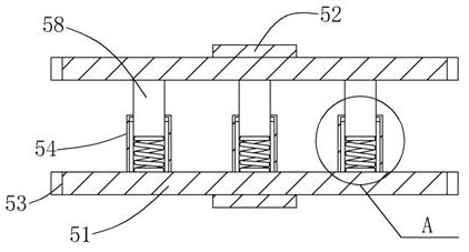
[0028] Specifically, the reinforcing device 5 includes two reinforcing plates 51 . One side of the two reinforcing plates 51 is respectively fixed to the engaging plates 52 , the engaging plates 52 are respectively clipped in the engaging grooves 101 , and the two ends of the reinforcing plates 51 are symmetrically and evenly fixed to many There are limit blocks 53, the limit blocks 53 are respectively clamped in the limit grooves 201, the other side of one reinforcing plate 51 is evenly fixed to the bottom surface of the plurality of fixing plates 54, and the top surface of the fixing plate 54 is evenly provided with a plurality of telescopic grooves 55. The inner wall of the telescopic groove 55 is symmetrically provided with a moving groove 56, and the moving blocks 57 are respectively clamped in the moving grooves 56. The moving blocks ...
Embodiment 3
[0031] see Figure 1 to Figure 4 , is the third embodiment of the present invention, which is based on the above two embodiments;
[0032] When the present invention is in use, one end of the support plate 2 is firstly fixed to one of the profile plates 1 through the fixing screws 4 and the mounting plate 3, and then the reinforcing device 5 is aligned with the engaging groove 101 on the profile plate 1 and the support plate 2 respectively. The limit slot 201 is clamped between the support plates 2, and then another profile plate 1 is pressed down to contact the reinforcement device 5, and is fixed to the support plate 2 through the fixing screws 4 and the mounting plate 3, and the reinforcement device 5 The reinforcing plates 51 in the middle contact the profile plate 1 respectively, and at the same time the anti-vibration rod 58 shrinks into the expansion groove 55 when the reinforcing plate 51 and the profile plate 1 are pressed down. 51 Increase the overall load-bearing s...
PUM
 Abstract
Description
Claims
Application Information
 - R&D
- Intellectual Property
- Life Sciences
- Materials
- Tech Scout
- Unparalleled Data Quality
- Higher Quality Content
- 60% Fewer Hallucinations
Browse by: Latest US Patents, China's latest patents, Technical Efficacy Thesaurus, Application Domain, Technology Topic, Popular Technical Reports.
© 2025 PatSnap. All rights reserved.Legal|Privacy policy|Modern Slavery Act Transparency Statement|Sitemap|About US| Contact US: help@patsnap.com


