Variable geometry combustion chamber diffuser structure and application

A diffuser and combustion chamber technology, applied in the field of combustion chamber diffuser structure, can solve the problems of unbalanced air flow, large pressure loss, large vortex, etc., and achieve high uniformity of outlet temperature distribution, high temperature peak value, and high performance Excellent effect

Active Publication Date: 2022-07-22
NORTHWESTERN POLYTECHNICAL UNIV
View PDF10 Cites 0 Cited by
  • Summary
  • Abstract
  • Description
  • Claims
  • Application Information

AI Technical Summary

Problems solved by technology

Because under normal circumstances, the air Mach number at the inlet of the aero-engine combustion chamber will reach about 0.3, and the absolute speed may reach 120-220m / s, and with the development of advanced aero-engines, the pressure ratio of the compressor will continue to increase, which will cause The speed is higher, but stable and reliable combustion cannot be organized at such a high speed, even if the pressure loss can be stabilized, the pressure loss will be large, and the pressure loss in the combustion chamber increases by 1%, and the unit fuel consumption rate increases by 0.5%, so the expansion Excessive pressure loss in the compressor is very unfavorable to flight costs, etc.
[0004] The main types of diffusers are streamlined diffuser and sudden diffuser, etc. The streamlined diffuser is very sensitive to machining errors because it cannot be balanced after the airflow is divided into different flow paths, and it will change with the change of working conditions. The performance of the diffuser has also changed greatly, but the diffuser performance of the streamlined diffuser is better
In order to solve the problem that the air flow of the streamlined diffuser cannot be rebalanced, scholars have proposed the sudden expansion diffuser, but the sudden expansion diffuser will inevitably produce a large vortex due to the existence of the sudden expansion area, so the pressure loss is relatively large

Method used


Image

  • Variable geometry combustion chamber diffuser structure and application
  • Variable geometry combustion chamber diffuser structure and application
  • Variable geometry combustion chamber diffuser structure and application

Examples


Embodiment

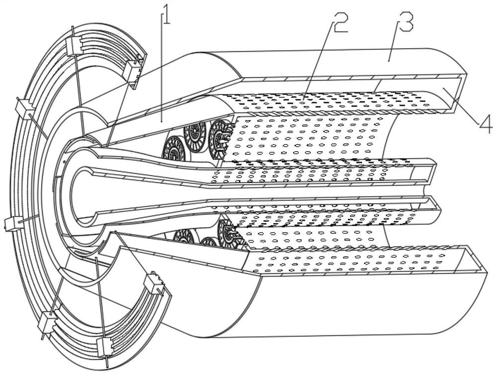
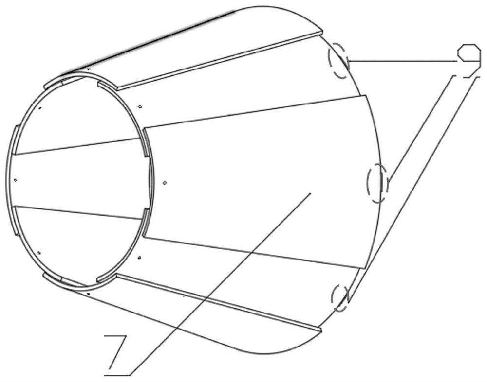
[0036] like figure 1 As shown, the outer diffuser 6 includes eight diffuser plates 7, and the angle occupied by each diffuser plate 7 is 60°, and the initial angle between two adjacent diffuser plates 7 is 45°. The angle will change, that is, the overlapping part between the two adjacent diffuser plates 7 will change. When the airflow demand at the head of the flame cylinder increases, the overlapping part between the diffuser plates 7 will decrease. When decreasing, the overlapping portion between the diffuser plates 7 increases, and the radial distance between two adjacent diffuser plates 7 is 1 mm, which ensures that the movement of each diffuser plate 7 does not interfere with each other and affects the air leakage at the same time. .

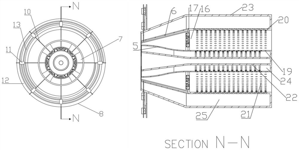
[0037] like figure 1 and image 3 As shown, the diffuser inlet control portion 8 includes a push-pull rod 10 , a moving block 11 , a gear 12 and a gear upper rail 13 . A stepper motor is used to drive the gear 12 to rotate, and the gear...


PUM


Abstract

The invention discloses a variable geometry combustor diffuser structure and application, and belongs to the field of gas turbine combustors. Comprising a diffuser, a flame tube, a casing and inner and outer ring cavities, and airflow flows into the inner and outer ring cavities and the head of the flame tube from a gas compressor and then flows into the flame tube to participate in combustion cooling and mixing; the diffuser comprises an inner diffuser and an outer diffuser; the outer diffuser comprises an outer diffuser plate, a diffuser inlet control part and a diffuser outlet connection part; the outer diffuser plate is formed by uniformly distributing a plurality of arc-shaped diffuser plates along the circumferential direction, and the edges of the adjacent diffuser plates are mutually overlapped; the diffuser inlet control part is installed at the front end of an outer diffuser plate, and the inner diameter change of an air inlet of the outer diffuser is achieved by adjusting the radial position of the front end of each diffuser plate. The rear end of the diffuser plate is hinged to the outer edge of a head flange plate of the flame tube in the circumferential direction through the diffuser outlet connecting part. The air inlet proportion of the annular cavity and the head of the diffuser under different working conditions is adjusted, so that the diffuser has a better effect under different working conditions.

Description

technical field [0001] The invention belongs to the field of gas turbine combustion chambers, and particularly relates to a variable geometry combustion chamber diffuser structure and application. Background technique [0002] The aero-engine is the "heart" of the aircraft, providing the power needed for the aircraft to fly, and the aero-engine combustion chamber is the "heart" of the "heart" of the aircraft, converting the chemical energy of the fuel into heat energy, driving the turbine to do work, and finally converting the fuel The chemical energy is converted into the mechanical energy of the engine. [0003] The diffuser is one of the most important components of the combustion chamber. It is the first component at the inlet of the combustion chamber. It mainly decelerates and supercharges the airflow entering the combustion chamber, so that the combustion can occur stably. Because in general, the Mach number of the air at the inlet of the aero-engine combustion chamb...

Claims


Application Information

Patent Timeline
Patent Type & Authority Applications(China)
IPC IPC(8): F23R3/04F23R3/42F23R3/58
CPCF23R3/04F23R3/42F23R3/58Y02T10/12
Inventor 闫玥索建秦梁红侠黎明张美月
Owner NORTHWESTERN POLYTECHNICAL UNIV
Why Eureka
Try Eureka