
A diffuser with a rectifier plate and its application

A rectifier plate and diffuser technology, which is applied in indirect carbon dioxide emission reduction, climate sustainability, combustion methods, etc., can solve the problems such as the inability to distribute and increase airflow, reduce internal pressure loss, and improve static pressure recovery. effect of size

Active Publication Date: 2022-07-05
NORTHWESTERN POLYTECHNICAL UNIV
View PDF16 Cites 0 Cited by
  • Summary
  • Abstract
  • Description
  • Claims
  • Application Information

AI Technical Summary

Problems solved by technology

[0004] In the last century, the United States NACA Report 949 proposed a method to solve the flow separation problem of a large expansion angle conical diffuser, that is, to place a flow baffle somewhere in the diffuser, and the baffle has the same size and uniform Arranged holes, this baffle is equivalent to a turbulence generator, which can increase the turbulence of the downstream flow, thereby inhibiting the separation in the diffuser with a large cone angle and improving the performance of the diffuser; however, this structure cannot affect the flow. Distribution, can only solve the flow separation of large cone angle diffusers, not applicable to other advanced combustion chambers

Method used


Image

  • A diffuser with a rectifier plate and its application
  • A diffuser with a rectifier plate and its application
  • A diffuser with a rectifier plate and its application

Examples


Embodiment Construction

[0033] The embodiments described below with reference to the accompanying drawings are exemplary, and are intended to explain the present invention and should not be construed as limiting the present invention.

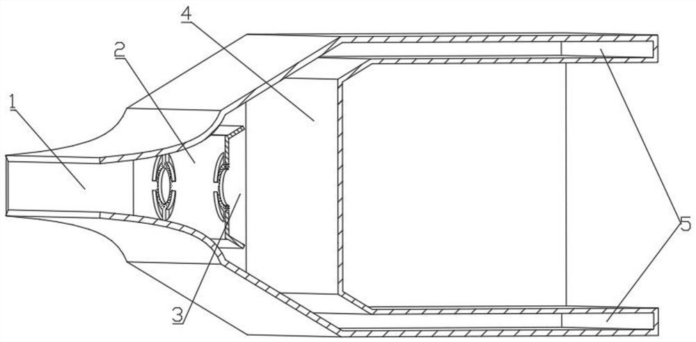
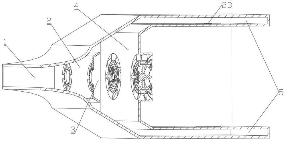
[0034] like figure 1 As shown, the present invention provides a diffuser structure with a rectifying plate, including a pre-diffuser 1 , a rectifying plate 2 , a sudden diffuser diffuser section 3 , a flame tube 4 and an inner and outer ring cavity 5 . The airflow flows out of the compressor and first flows into the pre-diffuser 1, then flows through the fairing plate 2 and enters the sudden diffusion and diffusion section 3, and then flows into the flame tube to participate in combustion cooling and mixing.

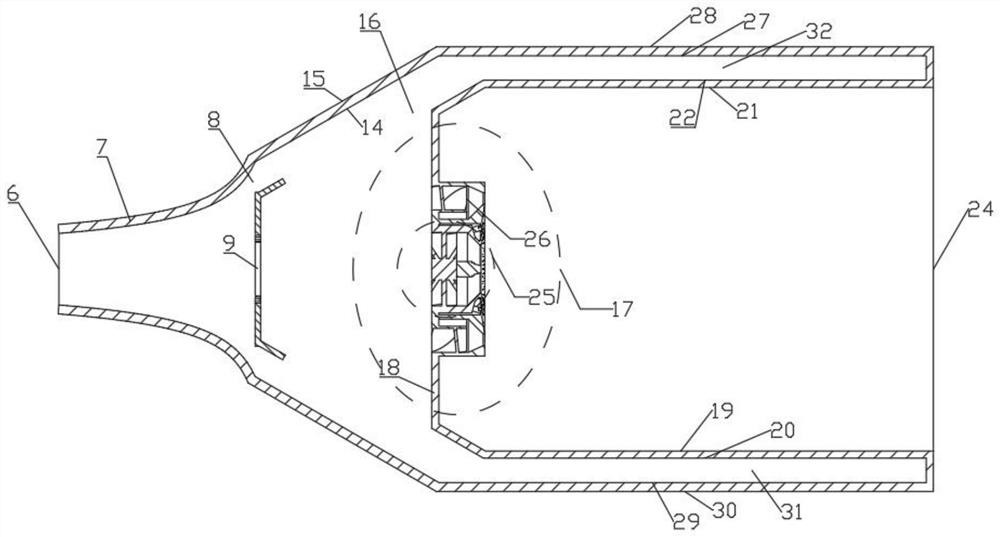
[0035] like figure 2 As shown, the pre-diffuser 1 is composed of a diffuser inlet 6 , a pre-diffuser wall 7 , and a pre-diffuser outlet 8 . The airflow flows along the wall 7 based on the isobaric gradient profile design, the flow near the wall does not separ...


PUM


Abstract

The invention relates to a diffuser with a rectifying plate and its application, belonging to the field of gas turbine combustion chambers; the diffuser comprises a pre-diffuser, a rectifying plate, a sudden diffuser and diffuser section, a flame tube and an inner and outer ring in sequence along the axial direction. Cavity, the fairing plate is located in the protruding diffuser section, the outlet of the pre-diffuser 1 is opposite to and perpendicular to the axial direction of the combustion chamber, including a guide hole and a guide plate; The heads of the flame cylinders are arranged in a one-to-one correspondence, including a circular hole in the center, a fan-shaped hole, a cooling hole and a deflector; a. The invention can effectively reduce the total pressure loss in the diffuser, reduce the useless loss in the combustion chamber, reduce the fuel consumption rate, and the total pressure loss is also within the acceptable range when the inlet Mach number is high; After reasonable and accurate distribution, it flows into various downstream components to further meet the aerodynamic requirements of advanced combustion chambers.

Description

technical field [0001] The invention belongs to the field of gas turbine combustion chambers, and in particular relates to a diffuser with a rectifying plate and its application. Background technique [0002] Compressor, combustion chamber and turbine are the three core components of aeroengine. In the thermodynamic cycle of the engine, the combustion chamber completes the constant pressure heating process, and its main function is to release the chemical energy in the fuel and convert it into heat energy, so as to increase the total enthalpy of the gas and improve the expansion of the gas in the turbine and the tail nozzle. Ability. From this point of view, the working quality of the combustion chamber directly affects the work and performance of the engine, so the performance of the combustion chamber directly determines the quality of the engine. [0003] Most of today's aero-engine compressor outlet airflow velocity is 170m / s or even higher, it is impossible to stabili...

Claims


Application Information

Patent Timeline
Patent Type & Authority Patents(China)
IPC IPC(8): F23R3/04
CPCF23R3/04Y02T50/60
Inventor 闫玥索建秦梁红侠李乐孙付军朱鹏飞冯翔洲李岳李前东
Owner NORTHWESTERN POLYTECHNICAL UNIV
Learn More