
Spatial heterodyne Raman spectrometer

A spectrometer and space technology, used in Raman scattering, using diffractive elements to generate spectra, instruments, etc., can solve the problems of troublesome optical path installation and calibration, small measurement range, troublesome, etc., to avoid complicated optical path calibration and realize the measurement band , the effect of simplifying the production process

Pending Publication Date: 2022-07-22
CHANGCHUN INST OF OPTICS FINE MECHANICS & PHYSICS CHINESE ACAD OF SCI
View PDF0 Cites 0 Cited by
  • Summary
  • Abstract
  • Description
  • Claims
  • Application Information

AI Technical Summary

Problems solved by technology

However, two gratings are placed on the two interference arms of the spatial heterodyne measurement method, and the angle between the grating angle and the optical axis is a specific Littrow angle, and the optical paths of the two arms must be equal; so the spatial heterodyne interferometer It is very troublesome to adjust and calibrate the optical path
In addition, in traditional spatial heterodyne measurement, only one grating can be placed on the two arms, and the measurement range is small; and if the angle of the grating needs to be adjusted to expand the measurement band, the gratings on the two arms have to be readjusted and calibrated separately, which is very troublesome

Method used


Image

  • Spatial heterodyne Raman spectrometer
  • Spatial heterodyne Raman spectrometer
  • Spatial heterodyne Raman spectrometer

Examples


Embodiment Construction

[0031] Hereinafter, embodiments of the present invention will be described with reference to the accompanying drawings. In the following description, the same modules are denoted by the same reference numerals. In the case of the same reference numerals, their names and functions are also the same. Therefore, its detailed description will not be repeated.

[0032] In order to make the objectives, technical solutions and advantages of the present invention clearer, the present invention will be further described in detail below with reference to the accompanying drawings and specific embodiments. It should be understood that the specific embodiments described herein are only used to explain the present invention, but not to limit the present invention.

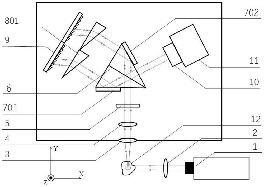
[0033] figure 1 A top view of the field of view broadening measurement of the optical path structure of the spatial heterodyne Raman spectrometer provided according to the embodiment of the present invention is shown.

[00...


PUM


Abstract

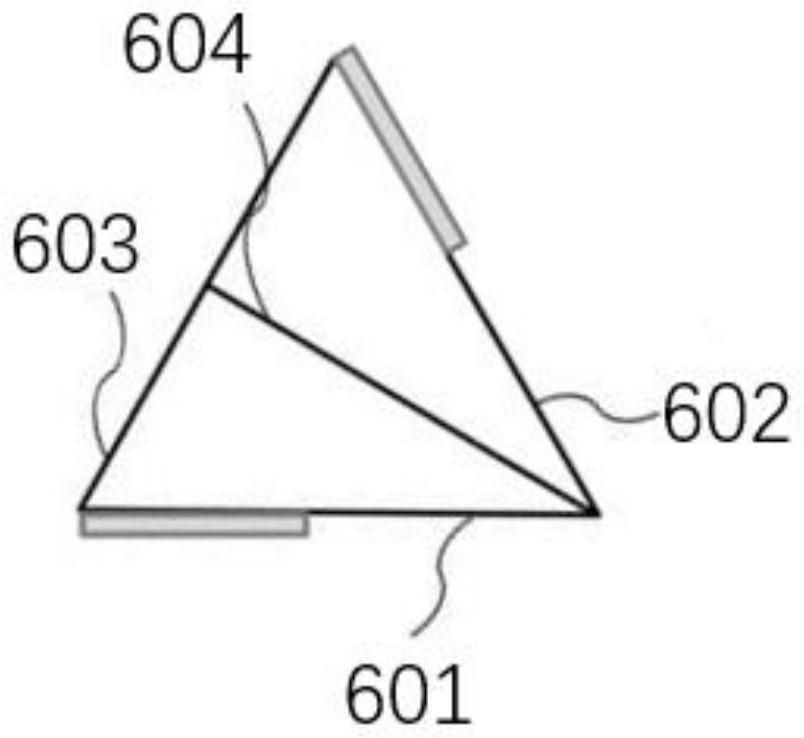
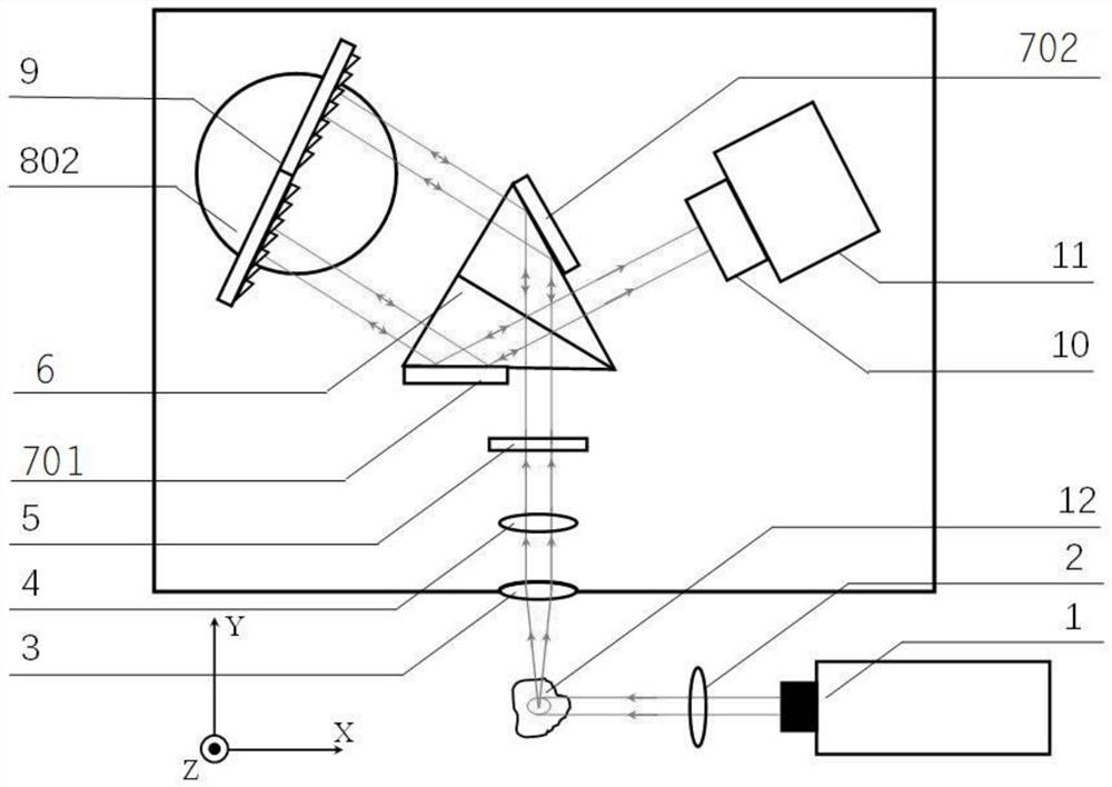
The invention provides a spatial heterodyne Raman spectrometer. The spatial heterodyne Raman spectrometer comprises a laser device, a collimating lens, a light filtering assembly, a beam splitter prism, a first reflector, a second reflector, a light beam turning device, a splicing grating and an imaging device, the laser device emits a laser beam to irradiate a sample and then emits a scattered beam, the scattered beam is converged by the collimating lens and filtered by the filter assembly, then enters the beam splitter prism and is divided into two beams by a beam splitting surface of the beam splitter prism, and the two parallel beams are reflected by the first reflector and the second reflector respectively and then are reflected by the laser device. After passing through the light beam turning device, the light beam enters the splicing grating to be diffracted to form Raman diffraction light, the Raman diffraction light vertically enters the beam splitter prism, and interference is performed in the beam splitter prism to form spatial heterodyne Raman interference light; and the spatial heterodyne Raman interference light is emitted from the beam splitter prism and then enters the imaging device to obtain a spatial heterodyne Raman signal. The device enables a wave band expansion mode to be simpler and more convenient, and has the advantages of wide measurement wave band range, simple optical path adjustment, compact structure and the like.

Description

technical field [0001] The invention relates to the technical field of spectral analysis instruments, in particular to a spatial heterodyne Raman spectrometer. Background technique [0002] Raman spectroscopy is a non-destructive detection method using inelastic Raman light scattering based on the characteristics of light-matter interaction. The incident laser excites the molecular system to be measured, thereby generating Raman scattered light with a frequency different from that of the incident light. By measuring the relative intensities of specific spectral components in the Raman scattering spectrum and their frequency shifts relative to the incident light, information about the molecular system under test can be obtained. [0003] Harlander et al. published the first spatial heterodyne Raman spectroscopy measurement method in 1992, using two separate gratings to generate spatial heterodyne interference, which improved the shortcomings of traditional Fourier spectromet...

Claims


Application Information

Patent Timeline
Patent Type & Authority Applications(China)
IPC IPC(8): G01J3/44G01J3/18G01J3/02G01N21/65
CPCG01J3/44G01J3/18G01J3/0205G01N21/65G01J2003/1208
Inventor 李晓天初启航吉日嘎兰图张博陈俊于宏柱孙雨琦
Owner CHANGCHUN INST OF OPTICS FINE MECHANICS & PHYSICS CHINESE ACAD OF SCI
Learn More