Multi-cell material complex loading system

A technology for complex loading and cellular materials, applied in the direction of analyzing materials, using stable tension/pressure testing material strength, force/torque/work measuring instruments, etc., can solve the problems of poor adhesion, unfavorable research verification, and impact testing and other problems, to achieve the effect of simple and effective installation, high collection accuracy and good universality

Pending Publication Date: 2022-07-22
CHANGAN UNIV
View PDF0 Cites 0 Cited by
  • Summary
  • Abstract
  • Description
  • Claims
  • Application Information

AI Technical Summary

Problems solved by technology

If the adhesive layer is too thin, it may lead to poor adhesion during the test, which will affect the completion of the test; if the adhesive layer is too thick, it will affect the accuracy of the test results. In the center of the system, the requirement of variable angle cannot be realized, which is not conducive to the development of the test
2. The data acquisition of the system is completed by the sensor on the testing machine, and complex loading requires data in at least two directions, so certain requirements are put forward for the sensor of the testing machine. When the sensor of the testing machine cannot measure data in two directions at the same time, The experimental data converted by multiplying the trigonometric function value of the angle must have a large error, which is not conducive to the research and verification
3. The size of the middle groove of the system limits the size of the test piece
Therefore the complicated loading system of prior art can't meet the needs of those skilled in the art

Method used


Image

  • Multi-cell material complex loading system
  • Multi-cell material complex loading system
  • Multi-cell material complex loading system

Examples


Embodiment Construction

[0030] In order to further illustrate the technical means and effects adopted by the present invention to achieve the predetermined purpose of the invention, the following in conjunction with the accompanying drawings and preferred embodiments, the specific embodiments, structures, features and effects of the application according to the present invention are described in detail as follows .

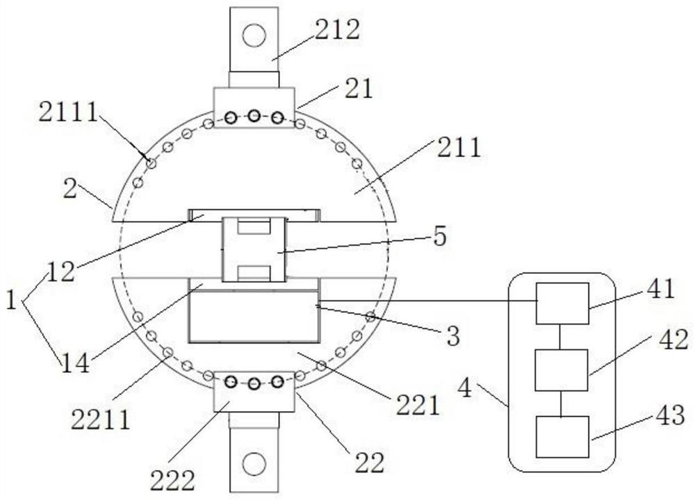
[0031] like figure 1 As shown, an embodiment of the present invention proposes a complex loading system for multicellular materials, which includes: a plurality of specimen clamping devices 1 , a loading condition angle adjustment device 2 , a stress monitoring device 3 and a data acquisition and analysis device 4 .

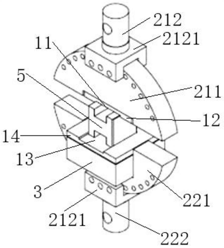
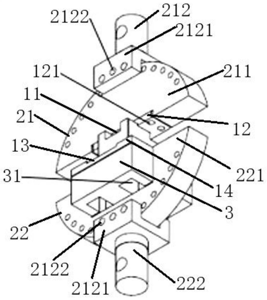
[0032] like Figure 1 to Figure 4As shown, the specimen clamping device 1 is provided with a rectangular space structure for installing and fixing the specimen 5 and matching the structural size of the specimen 5. Each of the specimen clamping devices 1 has a rectangular ...


PUM


Abstract

The invention discloses a multi-cell material complex loading system, which mainly adopts the technical scheme that a plurality of test piece clamping devices are arranged, and rectangular space structures which are used for mounting and fixing test pieces and are matched with the test piece structures in size are arranged on the test piece clamping devices; the rectangular space structures on the test piece clamping devices are different in size and are matched with different test piece structures in size; the loading working condition angle adjusting device comprises an upper loading working condition angle adjusting device and a lower loading working condition angle adjusting device, and the upper part of the test piece clamping device is embedded in the upper loading working condition angle adjusting device and is detachably connected with the upper loading working condition angle adjusting device; the lower part of the test piece clamping device is embedded on the lower part loading working condition angle adjusting device; the stress monitoring device is embedded on the lower loading working condition angle adjusting device and is detachably connected with the lower part of the test piece clamping device and the lower loading working condition angle adjusting device respectively; and the data acquisition and analysis device is connected with the stress monitoring device.

Description

technical field [0001] The invention relates to the technical field of mechanics research, in particular to a complex loading system of multicellular materials. Background technique [0002] In the study of mechanical properties of cellular materials, the mechanical behavior of material structures under complex stress states has become a major research hotspot. In order to better study the mechanical properties of materials, it is necessary to carry out relevant complex stress loading test verification. However, traditional universal testing machines and other testing devices can only perform unidirectional compression tests on materials, which cannot meet the needs of complex stress conditions; testing machines that can achieve complex loading, such as the plane biaxial testing system manufactured by MTS Corporation in the United States, are subject to Due to the high price, it is not universal. Therefore, a complex loading system based on a universal testing machine was ...

Claims


Application Information

Patent Timeline
Patent Type & Authority Applications(China)
IPC IPC(8): G01N3/04G01N3/02G01N3/08G01L5/00
CPCG01N3/04G01N3/02G01N3/08G01L5/00
Inventor 罗耿莫端钰刘浚哲柴成鹏赵剑南朱国华陈轶嵩
Owner CHANGAN UNIV
Why Eureka
Try Eureka