

Ejector pin type ball mounting jig
A ball-planting and thimble technology, which is applied in the manufacturing of electrical components, circuits, semiconductor/solid-state devices, etc., can solve the problems of affecting accuracy, contamination of the ball-mounting jig, and insufficient machining accuracy of the ball-mounting jig, so as to solve the problem of reducing precision and guaranteeing The effect of flatness
- Summary
- Abstract
- Description
- Claims
- Application Information
AI Technical Summary
Problems solved by technology
Method used
Image

Examples
Embodiment Construction
[0026] The technical solutions in the embodiments of the present invention will be clearly and completely described below with reference to the accompanying drawings in the embodiments of the present invention. Obviously, the described embodiments are only a part of the embodiments of the present invention, but not all of the embodiments. Based on the embodiments of the present invention, all other embodiments obtained by those of ordinary skill in the art without creative efforts shall fall within the protection scope of the present invention.
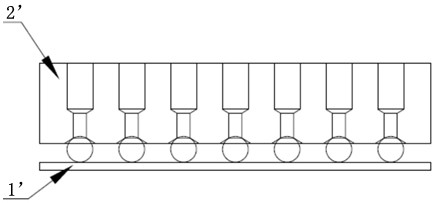
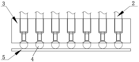
[0027] see Figure 2-7 , The ball planting fixture of the present invention includes a ball planting fixture 3, a needle plate 1, and a thimble 2. A needle plate 1 is added above the ball planting fixture 3, and a plurality of thimbles 2 are fixed in the needle plate 3. There are a plurality of pinholes 6 corresponding to the ejector pins 2 in the ball-mounting fixture 3, and a ball-suction hole 7 is opened at the head of the ball-mou...
PUM
 Abstract
Description
Claims
Application Information