Check patentability & draft patents in minutes with Patsnap Eureka AI!

Band-type brake device

A brake device and brake shaft technology, which is applied to brake parts, gear transmission mechanisms, brake types, etc., can solve problems such as shortened service life, excessive force, and component wear, and achieve reduced friction, enhanced stability, The effect of extending the service life

Pending Publication Date: 2022-07-26
厦门攸信测试机器人研究院有限公司
View PDF0 Cites 0 Cited by
  • Summary
  • Abstract
  • Description
  • Claims
  • Application Information

AI Technical Summary

Problems solved by technology

[0004] What the present invention aims to solve is the problem of uneven and excessive stress on the various parts of the existing brake device, which in turn leads to large wear among the parts and shortened service life.

Method used


Image

  • Band-type brake device
  • Band-type brake device
  • Band-type brake device

Examples


Embodiment Construction

[0026] The existing holding brake device has the problems of uneven force and indeterminate direction among the components, which in turn lead to large wear between the components and a shortened service life. Therefore, the present invention proposes a new solution. For a clearer representation, the present invention will be described in detail below with reference to the accompanying drawings.

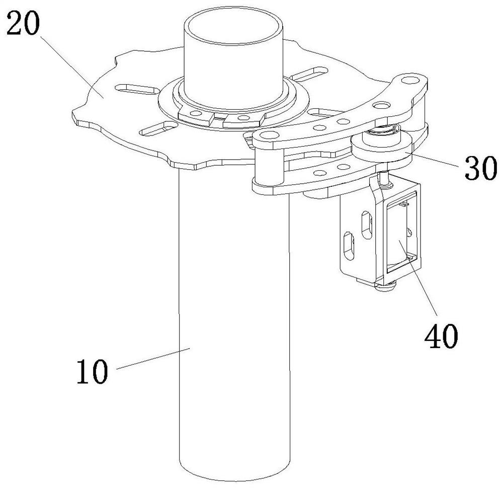
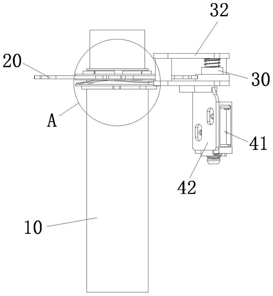
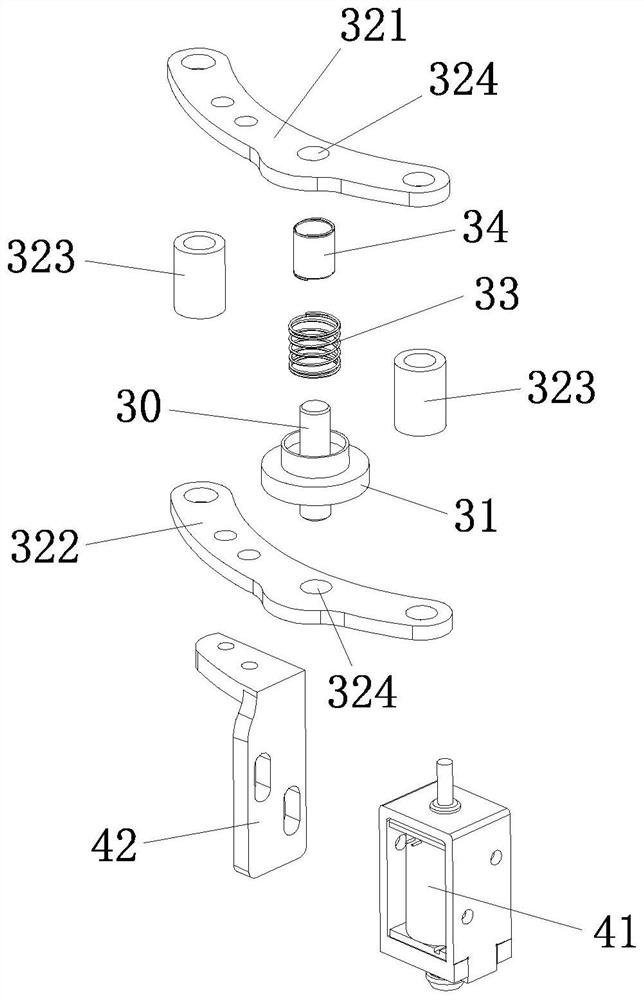
[0027] see Figure 1-3 , a holding brake device, including a turntable mechanism and a braking mechanism, the turntable mechanism includes a rotating shaft 10 and a brake disk 20 arranged on the rotating shaft 10, the braking mechanism includes a braking shaft 30 and a driving mechanism 40 , the axis of the rotating shaft 10 and the axis of the braking shaft 30 are parallel to each other, the braking shaft 30 is provided with a stop ring 31, and the driving mechanism 40 drives the braking shaft 30 to move up and down to make all the The stop ring 31 blocks or avoids the brake disc 2...


PUM


Abstract

The invention provides a band-type brake device which comprises a rotating disc mechanism and a braking mechanism, the rotating disc mechanism comprises a rotating shaft and a braking disc arranged on the rotating shaft, the braking mechanism comprises a braking shaft and a driving mechanism, the axis of the rotating shaft is parallel to the axis of the braking shaft, a check ring is arranged on the braking shaft, and the driving mechanism is arranged on the braking shaft. And the driving mechanism drives the brake shaft to move up and down so as to enable the stop ring to stop or avoid the brake disc. Braking is achieved through longitudinal cooperation of the brake disc and the brake shaft, the brake shaft bears force perpendicular to the axis, the whole brake shaft is evenly stressed, the braking stability is enhanced, and the service life of all components is effectively prolonged.

Description

technical field [0001] The invention relates to the field of motor brakes, in particular to a holding brake device. Background technique [0002] A holding brake is a brake control device that can quickly lock and release a rotary motion mechanism, so it is widely used in mechanical devices. However, in the existing brake device, the force between the brake mechanism and the turntable mechanism is uneven, and the force is too large, so that the mutual wear between the components is relatively large, and the service life of each component is shortened. SUMMARY OF THE INVENTION [0003] The purpose of the present invention is to provide a holding brake device. [0004] The present invention solves the problems of uneven force and excessive force among the components of the existing holding brake device, which in turn lead to large wear among the components and shortened service life. [0005] For realizing the purpose of the present invention, the technical scheme adopted ...

Claims


Application Information

Patent Timeline
Patent Type & Authority Applications(China)
IPC IPC(8): F16D63/00F16D65/02F16D65/14F16D121/20
CPCF16D63/006F16D65/02F16D65/14F16D2065/13F16D2121/20
Inventor 韩艺伟谢秋梅大森隼人叶火水
Owner 厦门攸信测试机器人研究院有限公司
Features
  • R&D
  • Intellectual Property
  • Life Sciences
  • Materials
  • Tech Scout
  • Unparalleled Data Quality
  • Higher Quality Content
  • 60% Fewer Hallucinations
Learn More