Accelerated fatigue test method for front subframe
A front subframe and fatigue test technology, applied in instrumentation, geometric CAD, design optimization/simulation, etc., can solve problems such as increasing product development cycle and cost, inability to optimize program verification, and affecting project development cycle, etc., to shorten fatigue Effect of test cycle, improvement of development efficiency, and reduction of cycle times
Pending Publication Date: 2022-07-26
CHONGQING CHANGAN AUTOMOBILE CO LTD
View PDF0 Cites 0 Cited by
- Summary
- Abstract
- Description
- Claims
- Application Information
AI Technical Summary
Problems solved by technology
[0003] The fatigue test period of a single-piece bench for a set of front sub-frame is about 100 hours or more (regardless of the construction time of the test tooling), and the general bench fatigue test verification requires at least three sets of parts, and a tes
Method used
View moreImage
Smart ImageViewing Examples

Examples
 PUM
 Abstract
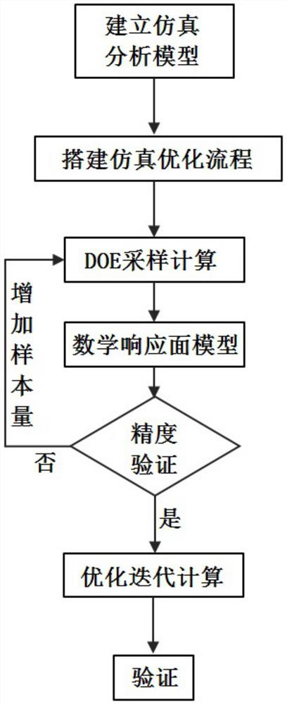
The invention discloses a front subframe accelerated fatigue test method, which comprises the following steps of: 1, establishing a simulation analysis model of a bench fatigue test of a front subframe, and performing quasi-static analysis; step 2, establishing a simulation optimization process based on a load scaling factor as a design variable, outputting a fatigue damage value with response as a key position, and carrying out DOE sampling calculation; 3, fitting a calculation result to obtain a mathematical response surface model meeting a precision requirement; step 4, according to the obtained mathematical response surface model, performing optimization by taking the load scaling factor as a variable, taking a fatigue damage value of a critical position as a constraint and taking a minimum damage target error as a target to obtain an optimal solution of the load scaling factor; and 5, calculating to obtain an optimized load, loading the front auxiliary frame, setting the cycle index as the optimized cycle target number, and carrying out a bench fatigue test. The fatigue test cycle index can be reduced, the fatigue test period is shortened, and the development efficiency is improved.
Description
technical field [0001] The invention relates to a bench fatigue test of auto parts, in particular to an accelerated fatigue test method of a front subframe. Background technique [0002] The component-level bench fatigue test is generally carried out before the test and verification of the whole vehicle and system. The purpose is to check the fatigue and durability problems of each product component in advance, so as to make the test and verification of the whole vehicle and system pass as much as possible at one time, which can shorten the development cycle. , reduce development costs. [0003] The fatigue test cycle of a single-piece bench for a set of front subframes is about 100 hours or more (not considering the time to build the test tool). Generally, at least three sets of parts are required for the verification of the bench fatigue test, and at least 15 days are required. It will greatly affect the project development cycle. In the process of test verification, if ...
Claims
Login to View More Application Information
Patent Timeline
 IPC IPC(8): G06F30/23G06F30/15G06F119/14
CPCG06F30/23G06F30/15G06F2119/14
Inventor 徒高桥龙弟德禹慧丽毛显红曾庆强董泽胡碧俊
Owner CHONGQING CHANGAN AUTOMOBILE CO LTD
Features
- R&D
- Intellectual Property
- Life Sciences
- Materials
- Tech Scout
- Unparalleled Data Quality
- Higher Quality Content
- 60% Fewer Hallucinations
Learn More Browse by: Latest US Patents, China's latest patents, Technical Efficacy Thesaurus, Application Domain, Technology Topic, Popular Technical Reports.
© 2025 PatSnap. All rights reserved.Legal|Privacy policy|Modern Slavery Act Transparency Statement|Sitemap|About US| Contact US: help@patsnap.com