[0027] In order to make it easy to understand the technical means, creation features, achieved goals and effects of the present invention, the present invention will be further described below with reference to the specific embodiments.
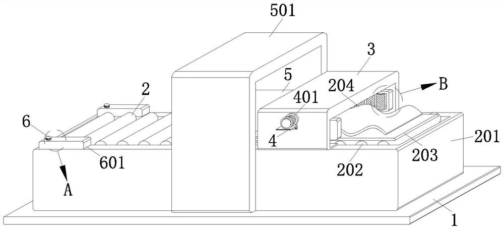
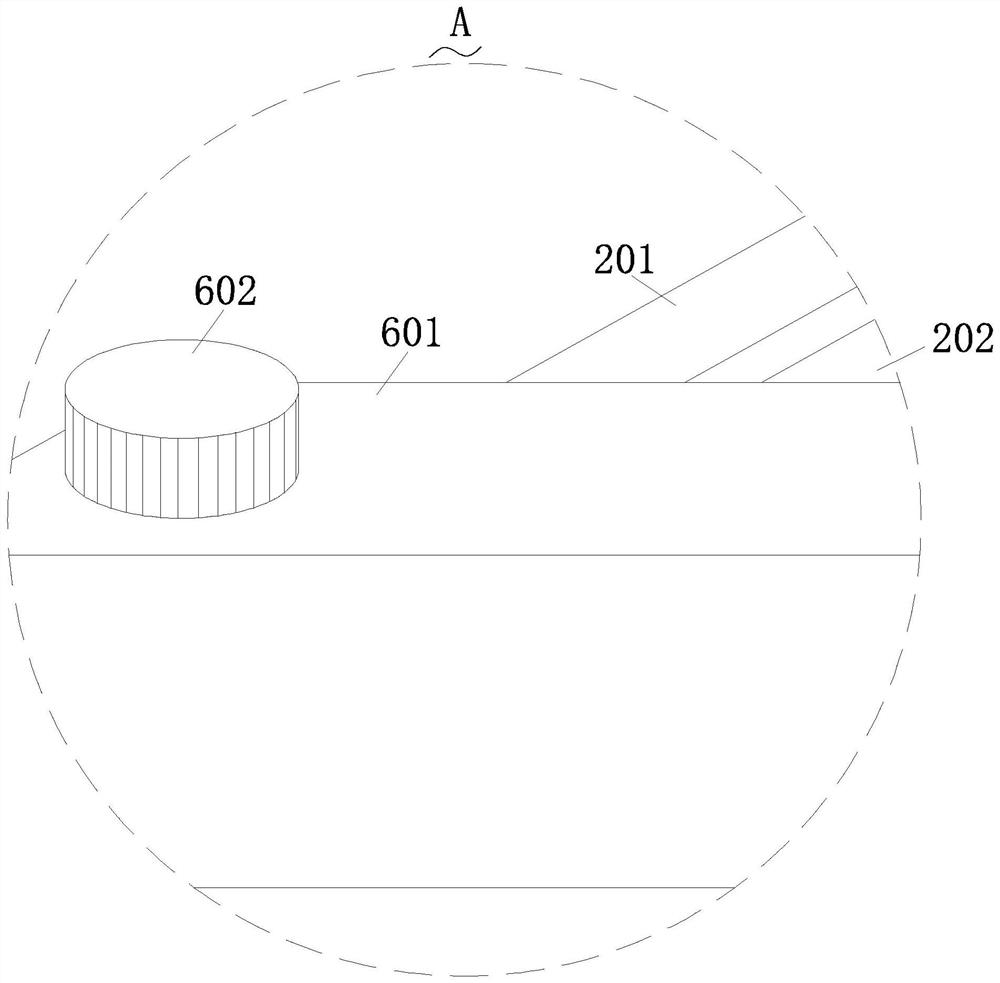
[0028] like Figure 1-Figure 10 As shown, a method for straightening a composite steel sheet according to the present invention includes a base plate 1, on which a conveying mechanism 2 is fixed; a fixing mechanism 3 is fitted on the conveying mechanism 2; A guide mechanism 4 is slid on the mechanism 3; a straightening mechanism 5 is installed on the transmission mechanism 2; a lubrication mechanism 6 is fixed on the transmission mechanism 2;
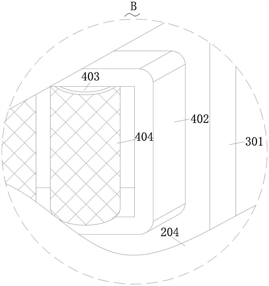
[0029] The fixing mechanism 3 includes a fixing frame 301, the guiding mechanism 4 includes a motor 401, the motor 401 is fixedly installed on the fixing frame 301, and the output end of the motor 401 is fixedly connected with a screw 405 through a coupling. The rotation directions of the threads at both ends of the screw rod 405 are opposite, the screw rod 405 is threadedly connected with a support rod 406, the support rod 406 is fixedly connected with a fixed block 402, and the fixed block 402 is fixedly connected with a number of connecting shafts 407 at equal distances. , a guide wheel 403 is rotatably connected to the connecting shaft 407, the screw 405 is rotatably connected to the fixing frame 301, a rubber pad 404 is adhered to the guide wheel 403, and the guide wheel 403 is connected to the fixing block 402. Rotate connection between.
[0030]Specifically, the fixing mechanism 3 further includes a sliding slot 302 , and a supporting rod 406 is slidable at the position of the sliding slot 302 , and two sliding rods 304 are symmetrically and fixedly connected to the fixing frame 301 , and the sliding rods 304 are sleeved The sleeve rod 303 is connected, and the sleeve rod 303 is fixedly connected with the fixing block 402. After the steel plate is placed on the conveying mechanism 2, the control switch of the guiding mechanism 4 can be turned on, so that the guiding mechanism 4 can slide in the fixing mechanism 3. , and then it is convenient to guide the steel plate when it is conveyed, which is beneficial to improve the processing effect of the steel plate, that is, the operator first places the bottom thick plate 203 on the conveying roller 202, and after fixing it, the composite steel plate 204 It is placed on the bottom pad 203, the fixing frame 301 is fixed on the worktable 201, the fixing frame 301 is fitted with a motor 401, the output end of the motor 401 is fixedly connected with a screw 405 through a coupling, and the screw 405 is threadedly connected There are two support rods 406, the screw threads at both ends of the screw rod 405 rotate in opposite directions, a fixed block 402 is fixedly connected to the support rod 406, a connecting shaft 407 is fixedly installed on the fixed block 402, and a guide wheel 403 is rotatably connected to the connecting shaft 407 to guide the A rubber pad 404 is adhered to the wheel 403. When the motor 401 starts, the screw 405 rotates in the fixing frame 301. When the screw 405 rotates, it drives the two support rods 406 to slide on the chute 302, and the support rod 406 slides, thereby making The fixed block 402 slides, the sleeve rod 303 is fixedly connected to the fixed block 402, the sliding rod 304 is fixedly installed on the fixed frame 301, and the fixed block 402 slides, so that the sleeve rod 303 slides along the sliding rod 304, because the guide wheel 403 is fixed When the block 402 rotates, when the fixed block 402 slides, the guide wheel 403 collides with the composite steel plate 204, and when the lower pad 203 drives the composite steel plate 204 to slide, the guide wheel 403 can be rotated to guide the composite steel plate 204. Therefore, it is beneficial to improve the processing effect of the composite steel sheet 204 .
[0031] Specifically, the conveying mechanism 2 includes a workbench 201 , a workbench 201 is fixedly connected to the bottom plate 1 , a plurality of rotating rods 205 are equidistantly connected to the workbench 201 , and the rotating rods 205 are fixedly connected There are conveying rollers 202, the conveying rollers 202 and the worktable 201 are rotatably connected, and the conveying rollers 202 are rollingly connected with the lower pad 203, and the lower pad 203 is fitted with a composite steel plate Sheet 204 .
[0032] Specifically, the straightening mechanism 5 includes an operating table 501 , an operating table 501 is fixedly connected to the bottom plate 1 , a hydraulic rod 502 is fixedly installed on the operating table 501 , and a support frame is matched and connected to the hydraulic rod 502 503, a long rod 504 is fixedly connected to the support frame 503, a straightening roller 505 is rotated on the long rod 504, and a plurality of the long rods 504 are arranged at an equal distance, and the straightening roller 505 and the support The racks 503 are rotated and connected, and the control switch of the conveying mechanism 2 is turned on, so that the steel plate can be conveyed when the conveying mechanism 2 rotates, and it is also convenient to transport the steel plate into the straightening mechanism 5, so that the straightening effect is better, namely: Then the operator turns on the control switch of the conveying roller table of the leveler, and then makes the rotating rod 205 drive the conveying roller 202 to rotate in the worktable 201. The rotating rod 205 and the conveying roller 202 are fixedly connected, and the lower pad 203 is placed on the On the conveying roller 202, when the conveying roller 202 rotates, the lower pad 203 can drive the composite steel sheet 204 to displace, thereby facilitating the transmission of the composite steel sheet 204, thereby helping to improve the processing effect of the composite steel sheet 204; When the roller 202 transfers the composite steel sheet 204 into the operating table 501, the operating table 501 is fixed on the base plate 1, the operating table 501 is fixedly installed with a hydraulic rod 502, and the hydraulic rod 502 is matched and connected with a supporting frame 503. The operating tables 501 are slidably connected, and a long rod 504 is fixedly installed on the support frame 503. The long rod 504 and the straightening roller 505 are rotatably connected. When the composite steel sheet 204 slides into the operating table 501, the operator can pass the straightening The control switch of the hydraulic rod 502 is turned on by the console of the straight machine. When the hydraulic rod 502 is activated, the support frame 503 can slide in the operation table 501, so that the straightening roller 505 can collide with the composite steel plate sheet 204 when sliding with the support frame 503. , thereby facilitating straightening of the bent composite steel sheet 204 .
[0033] Specifically, the lubricating mechanism 6 includes an oil storage tank 601 , two oil storage tanks 601 are symmetrically and fixedly connected to the workbench 201 , a sealing plug 602 is threadedly connected to the oil storage tank 601 , and the oil storage tank 601 is provided with Empty groove 605, a fiber sponge 603 is fixedly installed on the worktable 201, and a ball 604 is rotated on the fiber sponge 603. The ball 604 and the rotating rod 205 are rollingly connected, and the fiber sponge 603 is connected to the empty groove. 605 is connected, and the lubricating oil is injected into the lubricating mechanism 6. When the transmission mechanism 2 rotates, the lubricating oil in the lubricating mechanism 6 can lubricate the transmission mechanism 2, thereby helping to improve the use effect of the transmission mechanism 2, that is, working An oil storage tank 601 is fixedly connected to the table 201 , a sealing plug 602 is threadedly connected to the oil storage tank 601 , the bottom end of the oil storage tank 601 is provided with an inclined plane, an empty groove 605 is arranged on the oil storage tank 601 , and a fiber sponge is fixedly installed in the work table 201 603. There are balls 604 rotating on the table 201. The balls 604 conflict with the fiber sponge 603, and the balls 604 and the rotating rod 205 are rollingly connected. The operator opens the sealing plug 602 and injects lubricating oil into the oil storage tank 601. The bottom end of the oil tank 601 is set on an inclined plane, so that the lubricating oil can be easily discharged into the fiber sponge 603 through the hollow groove 605. When the rotating rod 205 rotates in the worktable 201, it can drive the ball 604 to rotate. When the ball 604 rotates, the fiber sponge 604 is rotated. 603 is squeezed, so that the lubricating oil in the fiber sponge 603 is applied to the ball 604, and the rotating rod 205 is rotated, so that the lubricating oil on the ball 604 can lubricate the rotating rod 205, which is beneficial to improve the rotating effect of the rotating rod 205. .
[0034] When the present invention is in use, first, the operator first places the bottom thick pad 203 on the conveying roller 202, and after fixing, the composite steel sheet 204 is placed on the bottom thick pad 203, and the fixing frame 301 is fixed on On the worktable 201, a motor 401 is installed on the fixing frame 301. The output end of the motor 401 is fixedly connected with a screw rod 405 through a coupling. The screw rod 405 is threadedly connected with two support rods 406. , a fixed block 402 is fixedly connected to the support rod 406, a connecting shaft 407 is fixedly installed on the fixed block 402, a guide wheel 403 is rotatably connected to the connecting shaft 407, and a rubber pad 404 is adhered to the guide wheel 403. When the motor 401 starts to start When the screw rod 405 rotates in the fixing frame 301, when the screw rod 405 rotates, it drives the two support rods 406 to slide on the chute 302, the support rods 406 slide, and then the fixed block 402 slides, and the fixed block 402 is fixedly connected with the sleeve rod 303 , a sliding rod 304 is fixedly installed on the fixing frame 301, and the fixing block 402 slides, so that the sleeve rod 303 slides along the sliding rod 304. Since the guide wheel 403 rotates in the fixing block 402, when the fixing block 402 slides, the guide wheel 403 and the The composite steel plate 204 is in conflict, and when the lower backing plate 203 drives the composite steel plate 204 to slide, the guide wheel 403 can guide the composite steel plate 204 when it rotates, thereby helping to improve the processing effect of the composite steel plate 204; then the operator Turn on the control switch of the conveying roller table of the leveler, and then make the rotating rod 205 drive the conveying roller 202 to rotate in the worktable 201. The rotating rod 205 and the conveying roller 202 are fixedly connected, and the bottom pad 203 is placed on the conveying roller 202. When the conveying roller 202 rotates, the lower backing plate 203 can drive the composite steel sheet 204 to displace, thereby facilitating the transmission of the composite steel sheet 204, thereby helping to improve the processing effect of the composite steel sheet 204; When the composite steel sheet 204 is transferred into the operation table 501, the operation table 501 is fixed on the base plate 1, the hydraulic rod 502 is fixedly installed on the operation table 501, and the hydraulic rod 502 is matched and connected with a support frame 503, and the support frame 503 and the operation table 501 A long rod 504 is fixedly installed on the support frame 503, and the long rod 504 and the straightening roller 505 are rotatably connected. When the composite steel plate sheet 204 slides into the operating table 501, the operator can control it through the straightening machine. The control switch of the hydraulic rod 502 is turned on by the stage. When the hydraulic rod 502 is activated, the support frame 503 can slide in the operation table 501, so that the straightening roller 505 can collide with the composite steel plate sheet 204 when sliding with the support frame 503, thereby facilitating the Straighten the bent composite steel plate sheet 204; an oil storage tank 601 is fixedly connected to the workbench 201, a sealing plug 602 is threadedly connected to the oil storage tank 601, the bottom end of the oil storage tank 601 is set on an inclined plane, and an empty space is provided on the oil storage tank 601. Slot 605 , a fiber sponge 603 is fixedly installed in the worktable 201, and a ball 604 is rotated on the worktable 201. The ball 604 collides with the fiber sponge 603, and the ball 604 and the rotating rod 205 are rollingly connected. The operator opens the sealing plug 602 to lubricate the The oil is injected into the oil storage tank 601. Since the bottom end of the oil storage tank 601 is set on an inclined plane, it is convenient for the lubricating oil to be discharged into the fiber sponge 603 through the hollow groove 605. When the rotating rod 205 rotates in the worktable 201, it can drive the balls When the ball 604 rotates, the fiber sponge 603 is squeezed when the ball 604 rotates, so that the lubricating oil in the fiber sponge 603 is applied to the ball 604, and the rotating rod 205 rotates, so that the lubricating oil on the ball 604 can lubricate the rotating rod 205. Therefore, it is beneficial to improve the rotation effect of the rotating rod 205 .
[0035] It will be apparent to those skilled in the art that the present invention is not limited to the details of the above-described exemplary embodiments, but that the present invention may be embodied in other specific forms without departing from the spirit or essential characteristics of the invention. Therefore, the embodiments are to be regarded in all respects as illustrative and not restrictive, and the scope of the invention is defined by the appended claims rather than the foregoing description, which are therefore intended to fall within the scope of the appended claims. All changes within the meaning and range of the equivalents of , are included in the present invention. Any reference signs in the claims shall not be construed as limiting the involved claim.
[0036] In addition, it should be understood that although this specification is described in terms of embodiments, not each embodiment only includes an independent technical solution, and this description in the specification is only for the sake of clarity, and those skilled in the art should take the specification as a whole , the technical solutions in each embodiment can also be appropriately combined to form other implementations that can be understood by those skilled in the art.