Ultrasonic stirring friction welding device and welding method

A friction welding and ultrasonic stirring technology, applied in welding equipment, welding equipment, auxiliary devices, etc., can solve the problems of high temperature of welding bath, residue, easy softening and deformation of welding materials, etc., to prevent relative movement and ensure stability.

Active Publication Date: 2022-07-29
JIANGSU JIAYI BEIKE OPTICS TECH CO LTD
View PDF6 Cites 2 Cited by
  • Summary
  • Abstract
  • Description
  • Claims
  • Application Information

AI Technical Summary

Problems solved by technology

[0004] The object of the present invention is to provide an ultrasonic friction stir welding device and a welding method to solve the following technical problems: (1) Solve the ultrasonic friction stir welding device in the prior art In the mobile welding process, usually only the stirring needle is in contact with the workpiece to be welded, which easily causes misalignment between the stirring needle and the workpiece to be welded, and the stability of the entire mobile welding cannot be guaranteed; (2) solve the technical problem in the prior art When the ultrasonic stir friction welding device is welding, the waste chips generated will remain in the welding tank, which will easily hinder the movement of the stirring pin. At the same time, the surface of the stirring pin will easily remain waste chips after welding, which will affect the technical problems of the subsequent welding of the stirring pin; 3) Solve the technical problem in the prior art that after welding by the ultrasonic friction stir welding device, the high-speed stirring treatment of the stirring needle leads to continuous high temperature in the welding tank, resulting in the easy softening and deformation of the welding material

Method used


Image

  • Ultrasonic stirring friction welding device and welding method
  • Ultrasonic stirring friction welding device and welding method
  • Ultrasonic stirring friction welding device and welding method

Examples


Embodiment 1

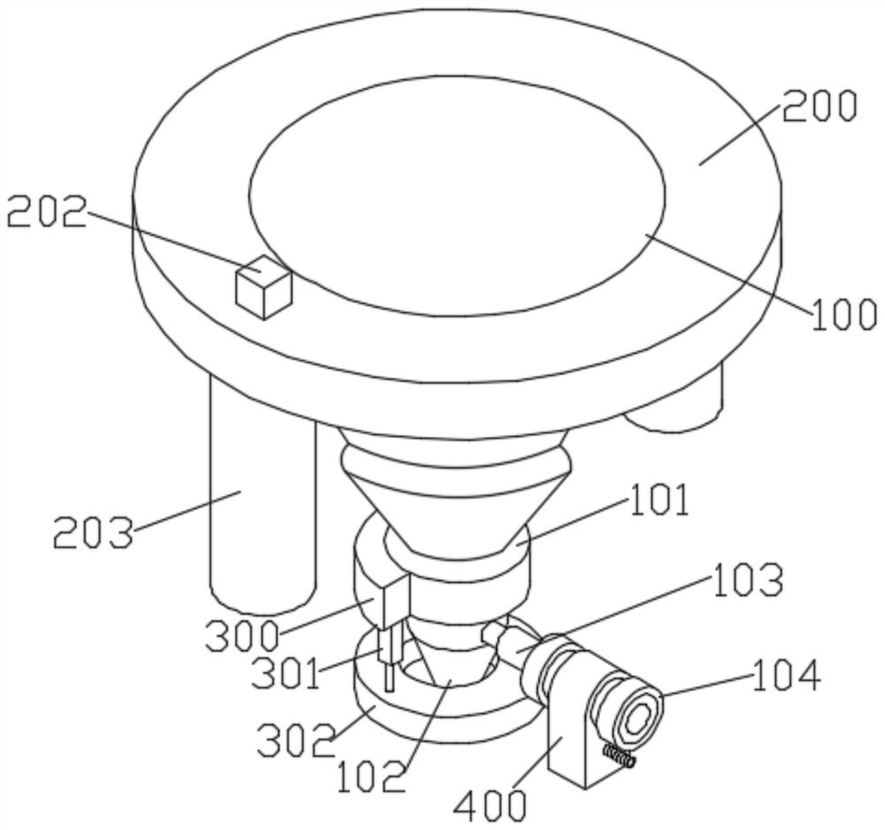
[0035] see figure 1 , Figure 7 As shown, the present invention is an ultrasonic friction stir welding device, which includes a mounting seat 100, a connecting piece 101, a static shaft shoulder 102, an ultrasonic probe 103, and a transducer 104. The connecting piece 101 is fixedly installed on the bottom of the mounting seat 100, and the static shaft The shoulder 102 is fixedly installed at the bottom of the connector 101, the bottom of the stationary shaft shoulder 102 is rotatably installed with a stirring needle, an ultrasonic probe 103 is installed on one side of the stationary shaft shoulder 102, and a transducer 104 is installed at one end of the ultrasonic probe 103 away from the stationary shaft shoulder 102, and the installation The outer ring of the seat 100 is rotatably connected to the annular casing 1 200. Two pressing and guiding mechanisms 203 are fixedly installed at the bottom of the annular casing 1 200. A fixing block 300 is installed on the connecting piec...

Embodiment 2

[0039] The present invention is an ultrasonic friction stir welding device, which includes a mounting seat 100, a connecting piece 101, a stationary shaft shoulder 102, an ultrasonic probe 103, and a transducer 104. The connecting piece 101 is fixedly installed on the bottom of the mounting seat 100, and the static shaft shoulder 102 is fixed Installed at the bottom of the connector 101, the bottom of the stationary shaft shoulder 102 is rotatably installed with a stirring needle, one side of the stationary shaft shoulder 102 is installed with an ultrasonic probe 103, and one end of the ultrasonic probe 103 away from the stationary shaft shoulder 102 is installed with a transducer 104, the transducer 104 A welding position cooling mechanism 400 is fixedly installed on the upper part.

[0040] see Figure 4-Figure 6 As shown, the welding position cooling mechanism 400 includes a fixed shell 401, the bottom of the fixed shell 401 is open, an inlet and outlet cylinder 402 is fixe...


PUM


Abstract

According to the ultrasonic stirring friction welding device and method, the outer ring of a mounting base is rotationally connected with a first annular sleeve shell, two pressing guide mechanisms are fixedly mounted at the bottom of the first annular sleeve shell, a fixing block is mounted on a connecting piece, and two adjusting assemblies are fixedly mounted at the bottom of the fixing block; the ends of piston rods of the two adjusting assemblies are connected with a scrap removing mechanism, and a welding position cooling mechanism is fixedly installed on the transducer. Through the arrangement of the lifting assembly, the guide wheels can be driven to ascend and descend, so that the guide wheels make contact with the surface of a to-be-welded part, meanwhile, the angles of the guide wheels are adjusted through the connecting assembly, and the guide wheels are adjusted to be parallel to the movable welding direction; according to the ultrasonic stirring friction welding device, the guide wheels can play a guiding role when the whole ultrasonic stirring friction welding device moves for welding, the guide wheels make contact with the to-be-welded parts, relative movement between the ultrasonic stirring friction welding device and the two to-be-welded parts can be prevented, and the stability of the whole moving welding process is guaranteed.

Description

technical field [0001] The invention relates to the technical field of welding, in particular to an ultrasonic friction stir welding device and a welding method. Background technique [0002] Friction stir welding is an advanced solid-phase joining technology with small welding deformation, green and pollution-free. Static shoulder friction stir welding is a new welding technology based on friction stir welding. Compared with traditional friction stir welding, it has the advantages of low welding heat input and beautiful weld without thinning. In the static shoulder friction stir welding process, since the static shoulder does not rotate, there is a large forward resistance and rotational torque between the stirring tool and the workpiece to be welded, and the life of the welding tool is low. Loading ultrasonic can solve the above problems . [0003] The prior art with application number CN202110122000.9 discloses an ultrasonic friction stir welding device and a welding me...

Claims


Application Information

Patent Timeline
Patent Type & Authority Applications(China)
IPC IPC(8): B23K20/10B23K20/12B23K20/26B23K37/00
CPCB23K20/10B23K20/122B23K20/26B23K37/003B23K37/00Y02P70/10
Inventor 张耀孟威
Owner JIANGSU JIAYI BEIKE OPTICS TECH CO LTD
Why Eureka
Try Eureka