Large-screen display for mobile emergency target detection vehicle
A target detection and display technology, applied in vehicle parts, transportation and packaging, etc., can solve problems such as viewing, and achieve the effect of improving service life, facilitating operation and viewing, and improving observation comfort.
- Summary
- Abstract
- Description
- Claims
- Application Information
AI Technical Summary
Problems solved by technology
Method used
Image

Examples
Embodiment 1
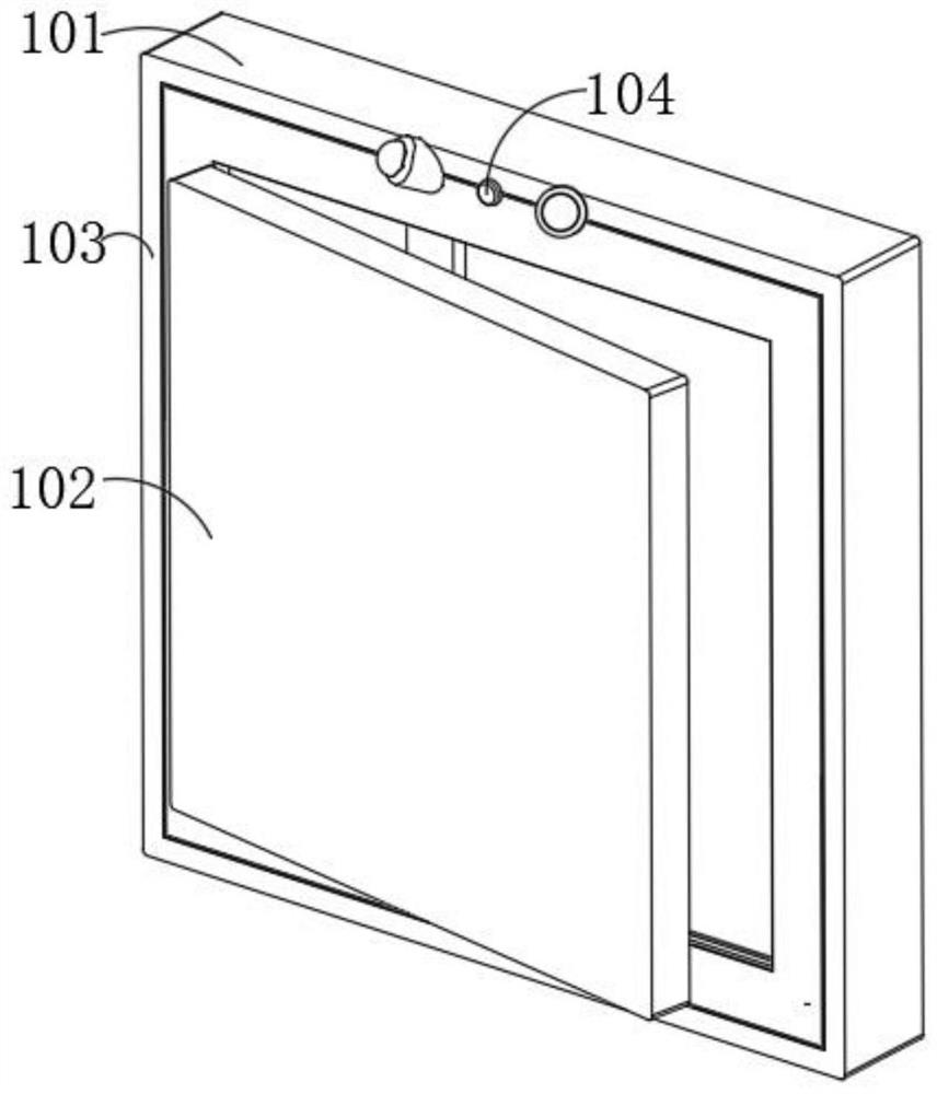
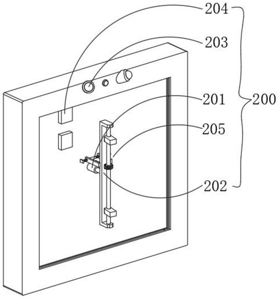
[0034] combine figure 1 , 2 , 3 and 4, a large-screen display for a mobile emergency target detection vehicle provided by the present invention includes a casing 101, a frame body 103 fixed on the casing 101, and a display panel 102 arranged on the casing 101. The casing 101 A push mechanism 200 for pushing the display panel 102 to the outside of the housing 101 is provided inside. The housing 101 is provided with an adjustment mechanism 300 that drives the display panel 102 to shift to the passenger side. 102 The external protection mechanism 400, the push mechanism 200 includes an electric push rod 201 fixed in the casing 101, the output end of the electric push rod 201 is fixedly connected with a transmission frame 202, and the transmission frame 202 is provided with a rotating way for the display panel 102 is facing the offset part 205 on the side of the main driver, a camera 203 is installed obliquely on the casing 101, and a visual sensor 204 is arranged in the casing 1...
Embodiment 2
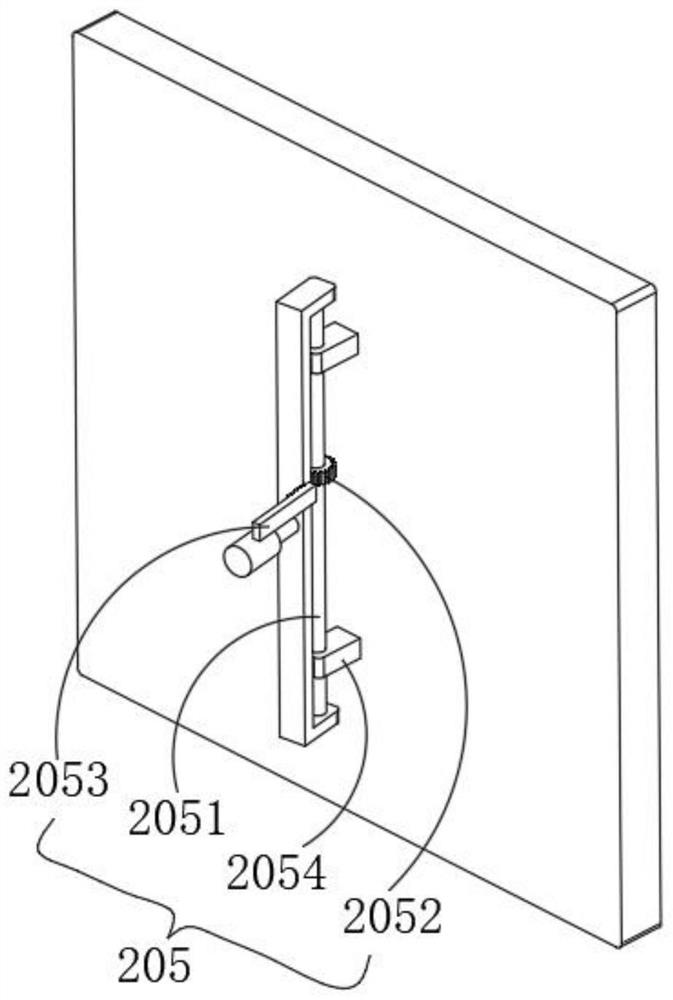
[0040] combine figure 1 , 2As shown in and 5, on the basis of the first embodiment, the adjustment mechanism 300 includes a first motor 301 fixed in the housing 101, a second rack 303 is provided on one side of the gear 2052, the second rack 303 and the first gear The rods 2053 are screwed on both sides of the bidirectional screw rod 302 respectively, and the ends of the second rack 303 and the first rack 2053 are attached to the inner wall of the housing 101. When the co-pilot needs to observe and operate the display panel 102, the first motor 301 is activated, so that the first rack 2053 and the second rack 303 on the bidirectional screw 302 move in opposite directions, the first rack 2053 is disengaged from the gear 2052, and when the second rack 303 is engaged with the gear 2052 for transmission, the operation of the push mechanism 200 is repeated. In this step, the display panel 102 can be shifted to the co-pilot, which is convenient for the co-pilot staff to operate and...
Embodiment 3
[0044] combine figure 1 , 6 As shown in Fig. 7, on the basis of the first embodiment, the protection mechanism 400 includes a second motor 401 fixed on the frame body 103, and the output end of the second motor 401 extends to the inside of the frame body 103 and is fixed with a transmission roller 402 , the drive roller 402 is wound with a sealing sheet 403, the upper and lower sides of the end face of the sealing sheet 403 are fixed with a slider 405, a tension spring 404 is fixed between the slider 405 and the inner wall of the frame 103, and the sealing sheet 403 passes through The chute is slidably connected to the inner wall of the frame body 103. When the display panel 102 is not in use, the second motor 401 starts to drive the drive roller 402 to rotate for unwinding, and then the tension spring 404 pulls the sealing sheet 403 through the slider 405 so that the sealing sheet 403 is laid on the surface. The surface of the display panel 102 can then be dust-proofed to pr...
PUM
 Abstract
Description
Claims
Application Information