
Mechanical clamping arm for unmanned aerial vehicle

A technology of unmanned aerial vehicles and mechanical clamps, which is applied in the field of unmanned aerial vehicles, can solve the problems of unfastened clamping of the parts to be clamped, and achieve the effect of improving the clamping and fixing effect and clamping stability

Pending Publication Date: 2022-07-29
国网浙江省电力有限公司三门县供电公司 +1
View PDF0 Cites 0 Cited by
  • Summary
  • Abstract
  • Description
  • Claims
  • Application Information

AI Technical Summary

Problems solved by technology

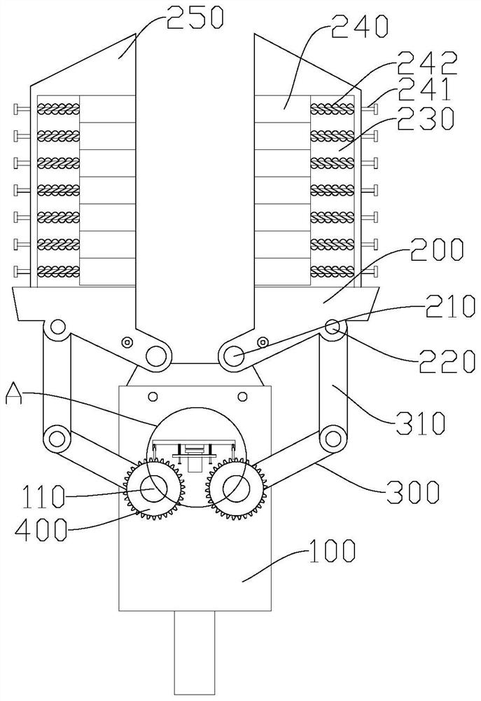
[0003] The technical problem to be solved by the present invention is to overcome the deficiencies of the prior art and propose a mechanical clamping arm for drones, which solves the problem that the existing mechanical clamping arm of the drone does not clamp the clamping parts firmly

Method used


Image

  • Mechanical clamping arm for unmanned aerial vehicle
  • Mechanical clamping arm for unmanned aerial vehicle
  • Mechanical clamping arm for unmanned aerial vehicle

Examples


Embodiment Construction

[0045] The technical solutions of the embodiments of the present invention will be explained and described below with reference to the accompanying drawings of the embodiments of the present invention, but the following embodiments are only preferred embodiments of the present invention, not all. Based on the examples in the implementation manner, other examples obtained by those skilled in the art without creative work all belong to the protection scope of the present invention.

[0046] In the description of the present invention, it should be understood that the terms "center", "longitudinal", "lateral", "length", "width", "thickness", "upper", "lower", "front", " The orientation or positional relationship indicated by "back", "left", "right", "vertical", "horizontal", "top", "bottom", "inside", "clockwise", "counterclockwise", etc. The orientation or positional relationship shown in the figures is only for the convenience of describing the present invention and simplifying...


PUM


Abstract

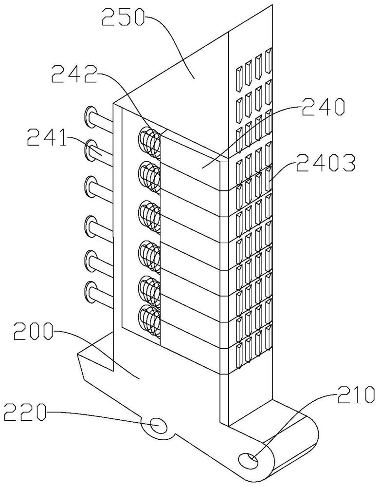
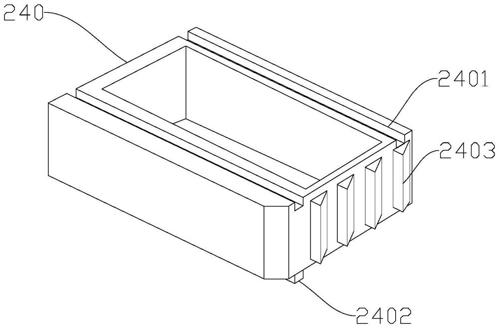
The invention relates to the technical field of unmanned aerial vehicles, in particular to a mechanical clamping arm for an unmanned aerial vehicle. The mechanical clamping arm comprises a machine shell connected with the unmanned aerial vehicle, a connecting rod assembly and clamping jaws hinged to the two sides of the front end of the machine shell, two motor shafts driven by a servo motor are arranged on the surface of the machine shell, and a plurality of movable blocks are sequentially arranged on the sides, close to each other, of the two clamping jaws in the longitudinal direction; when a motor shaft rotates to drive the two clamping jaws to be opened and closed oppositely through a connecting rod assembly so as to clamp a to-be-clamped part, the movable block making contact with the to-be-clamped part is extruded, compresses the pressure spring assembly and then moves. According to the mechanical clamping arm for the unmanned aerial vehicle, the problems that an existing mechanical clamping arm for the unmanned aerial vehicle cannot firmly clamp the to-be-clamped part and the part is prone to falling off during transportation are solved, and the clamping stability of the mechanical clamping arm for the parts of different shapes is effectively enhanced.

Description

【Technical field】 [0001] The invention relates to the technical field of unmanned aerial vehicles, in particular to a mechanical clamping arm for unmanned aerial vehicles. 【Background technique】 [0002] At present, when some high-altitude lines are being repaired, some maintenance tools used in transmission lines are easy to fall off during use or transmission. If you manually return to the starting point to pick up the corresponding tools, the maintenance time and cost will undoubtedly increase. The man-machine uses the mechanical gripper arm to transport the toolbox or parts waiting to be gripped at high altitude. The existing UAV mechanical gripper has the problem of not firmly gripping the parts to be gripped with different shapes, and at the same time gripping some toolboxes When a relatively heavy object is used, the clamping jaws of the mechanical clamping arm are prone to loosening during transportation, and the problem of the clamping parts falling off during trans...

Claims


Application Information

Patent Timeline
Patent Type & Authority Applications(China)
IPC IPC(8): B64D1/22B25J15/00
CPCB64D1/22B25J15/00
Inventor 王芳王帆张鹏飞王明燕杨泽亮蒋智勇郑聪
Owner 国网浙江省电力有限公司三门县供电公司
Learn More