Transportation method used in steel pipe machining process

A transportation method and technology of processing process, which is applied in the field of steel pipe processing, can solve the problems of easily falling and injuring operators, low safety, and low transportation efficiency, and achieve simple internal structure transformation, high transportation efficiency, and high safety Effect

Pending Publication Date: 2022-07-29
康景许
View PDF0 Cites 0 Cited by
  • Summary
  • Abstract
  • Description
  • Claims
  • Application Information

AI Technical Summary

Problems solved by technology

[0003] In the process of steel pipe processing, it is usually necessary to move the steel pipe. The existing mobile transportation device for steel pipe processing usually uses hoisting to move the steel pipe to the device and then transports it. It cannot maintain stability in the middle, and it is easy to fall and injure the operators on site, which has low safety.
[0004] The existing mobile transportation device for steel pipe processing is not stable enough to fix the steel pipe during the process of transporting the steel pipe. Due to the hoisting method, only one steel pipe can be transported at a time. Not only the stability is low, but also the transportation efficiency is low

Method used


Image

  • Transportation method used in steel pipe machining process
  • Transportation method used in steel pipe machining process
  • Transportation method used in steel pipe machining process

Examples


Embodiment 1

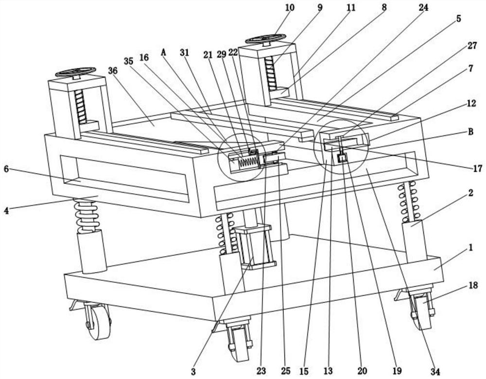
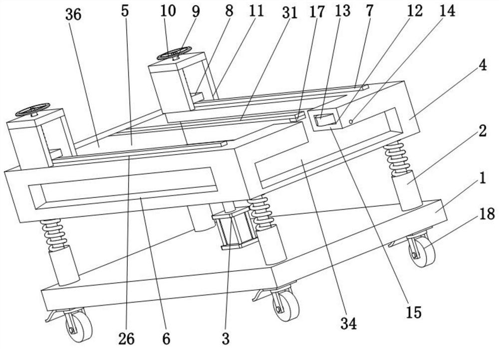
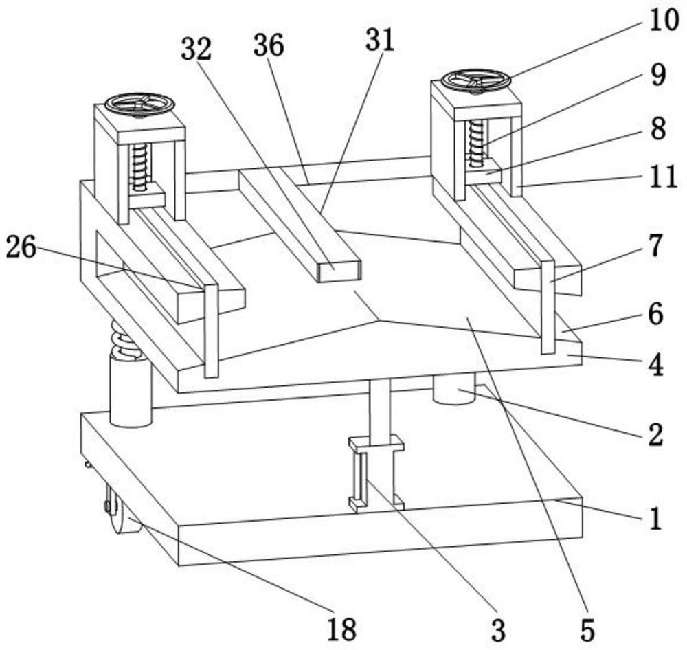
[0036] like Figure 1 to Figure 8As shown, the present invention provides a mobile transportation device for steel pipe processing, comprising a base 1, a cylinder 3 is fixedly installed in the middle of the top surface of the base 1, and a workbench 4 located directly above the base 1 is fixedly installed at the telescopic end of the cylinder 3 , the four corners of the top of the base 1 are fixedly installed with a buffer fixing device 2, and the buffer fixing device 2 is fixedly connected with the bottom of the workbench 4. The top of the workbench 4 is provided with a placement area 5, and the right side of the workbench 4 is provided with an inlet pipe Port 15, the inlet port 15 is communicated with the placement area 5, the right side of the inlet port 15 is provided with a wheel groove 12, the inside of the wheel groove 12 is movably sleeved with the driving wheel 13 through the bearing 27, and the inside of the workbench 4 is provided with a The motor seat cavity 19 di...

Embodiment 2

[0046] In use, the applicant found that the length of steel pipes is often long. In Example 1, the device can transport more steel pipes at a time, which solves the problem that only one steel pipe can be transported at a time when the existing steel pipes are moved and transported. Only steel pipes whose length is less than the length of the device can be transported. In order to solve the problem of transporting longer steel pipes, on the basis of Example 1, the applicant has opened a through hole 34 below the pipe inlet 15, and the through hole 34 is connected to the pipe inlet 15. At the same time, the applicant has a second airbag 30 fixedly connected to the left side of the workbench 4 , and a movable plate 36 is fixedly connected to the other side of the second airbag 30 , and the shape of the movable plate 36 is the same as that of the left side of the workbench 4 . The shape is the same and is slidably connected to the front and rear sides of the workbench 4. The secon...


PUM


Abstract

The invention belongs to the technical field of steel pipe machining, and discloses a transportation method used in the steel pipe machining process. According to the method, a steel pipe is placed in a pipe inlet, the steel pipe is placed between a driving wheel and the pipe inlet, the steel pipe is clamped by the driving wheel and the pipe inlet under the action of a spring, and the driving wheel is driven by a motor to rotate; and through the arrangement of a through hole, a second air bag, a third air bag and a fixing block, the device achieves collection and transportation of the long steel pipes, the problem that the steel pipes are prone to falling off and injuring workers due to the fact that traditional steel pipe hoisting is not stable is solved, and the steel pipe hoisting device has the advantages of being good in stability and high in safety.

Description

technical field [0001] The invention belongs to the technical field of steel pipe processing, in particular to a transportation method used in the steel pipe processing process. Background technique [0002] Steel pipes are steels with a hollow section whose length is much greater than the diameter or perimeter. According to the shape of the section, they are divided into round, square, rectangular and special-shaped steel pipes; according to the material, they are divided into carbon structural steel pipes, low alloy structural steel pipes, and alloy steel pipes. Steel pipes and composite steel pipes; according to their uses, they are divided into transportation pipelines, engineering structures, thermal equipment, petrochemical industry, machinery manufacturing, geological drilling and high-pressure equipment steel pipes, etc.; according to the production process, they are divided into seamless steel pipes and Welded steel pipes, of which seamless steel pipes are divided i...

Claims


Application Information

Patent Timeline
Patent Type & Authority Applications(China)
IPC IPC(8): B65G47/74B65G47/82
CPCB65G47/74B65G47/82
Inventor 康景许
Owner 康景许
Why Eureka
Try Eureka