Super high-rise core tube variable cross-section inclined wall hanging frame and construction method
A core tube and variable cross-section technology, which is used in the attachment of scaffolding, scaffolding supported by building structures, buildings, etc., to achieve the effect of improving safety and facilitating construction.
- Summary
- Abstract
- Description
- Claims
- Application Information
AI Technical Summary
Problems solved by technology
Method used
Image

Examples
Embodiment 1
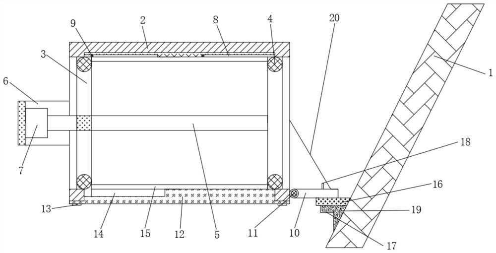
[0033] A super high-rise core tube variable-section inclined wall hanger, the hanger is located on the outer side of the inclined wall 1 , and the hanger includes an outer frame 2 and an inner frame 3 .
[0034] One side of the outer frame 2 is set to pass through the opening, the other side of the outer frame 2 is provided with a horizontally installed telescopic rod 7, the lower end of the outer frame 2 is installed with a bottom plate 12, and the outer wall of the lower end of the outer frame 2 located on one side of the opening is rotatably installed. Turning plate 10, the free end of the turning plate 10 is connected to the outer frame 2 through the pull rope 20, the lower end of the inner frame 3 is provided with a sealing plate 15, the inner frame 3 is slidably inserted into the inner cavity of the outer frame 2, one end of the inner frame 3 is Connecting the telescopic rod 7 , the other side of the inner frame 3 is slid and inserted laterally along the opening of the ou...
Embodiment 2
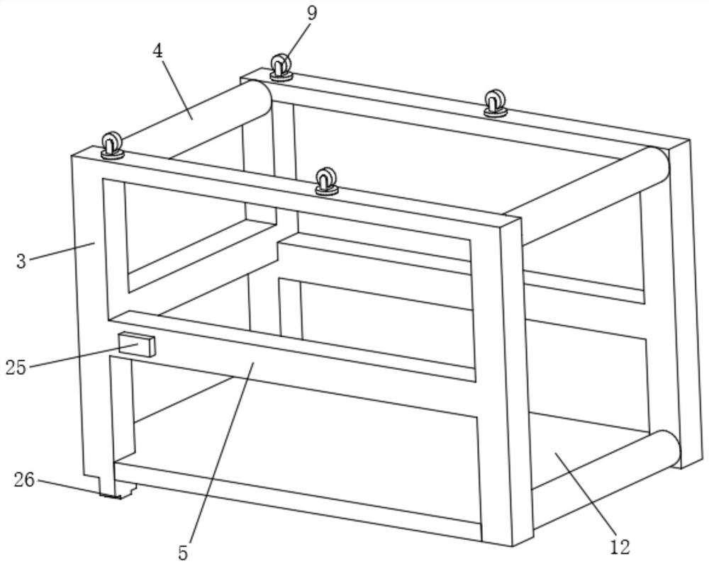
[0038] On the basis of Embodiment 1, in order to limit the position of lateral sliding and prevent lateral deviation, the present application also has a side frame 6 provided on the outer side of the outer frame 2, and the front and rear sides of the inner frame 3 are connected by four groups of matrix distributed The rod 4 is connected, a frame-shaped middle beam 5 is arranged in the middle of the inner frame 3, one end of the telescopic rod 7 is fixed on the side frame 6, the other end of the telescopic rod 7 is installed on the side wall of the middle beam 5, and the outer frame 2 Side plates 27 are arranged on the front and rear sides of the middle, a roller groove 8 is arranged on the inner wall of the upper end of the outer frame 2, a positioning groove 31 is arranged on the inner side of the side plate 27, and a slider 25 is arranged on the front and rear sides of the middle beam 5, and the slider 25 slides It is inserted into the positioning groove 31 , and the moving w...
Embodiment 3
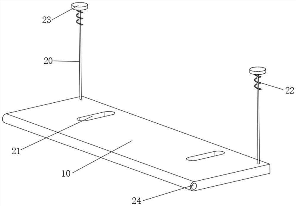
[0041] On the basis of Embodiment 2, in order to avoid the collision between the flap 10 and the outer wall of the high-rise caused by the lifting movement, the present application also has a through hole 30 provided at the end of the positioning groove 31, and a hinge seat is provided on the outer lower end of the outer frame 2 11. One end of the flap 10 is provided with a sleeve 24, the sleeve 24 is rotatably sleeved on the hinge base 11, the free end of the flap 10 is connected to one end of the pull rope 20, and the other end of the pull rope 20 extends along the through hole 30 to In the positioning slot 31, the end of the pull rope 20 is provided with a stopper 23, the stopper 23 is slidably installed in the positioning slot 31, a spring 22 is arranged between the stopper 23 and the inner wall of the positioning slot 31, and the spring 22 is sleeved on the puller. on rope 20.
[0042] By arranging the cooperation between the pull rope 20 and the spring 22, the elastic st...
PUM
 Abstract
Description
Claims
Application Information
 - R&D
- Intellectual Property
- Life Sciences
- Materials
- Tech Scout
- Unparalleled Data Quality
- Higher Quality Content
- 60% Fewer Hallucinations
Browse by: Latest US Patents, China's latest patents, Technical Efficacy Thesaurus, Application Domain, Technology Topic, Popular Technical Reports.
© 2025 PatSnap. All rights reserved.Legal|Privacy policy|Modern Slavery Act Transparency Statement|Sitemap|About US| Contact US: help@patsnap.com