
System and method for automatically judging residual magnetism of transformer of power plant

A discrimination method and transformer technology, applied in the direction of the size/direction of the magnetic field, magnetic performance measurement, etc., can solve the problems of expensive inspection, test time, power loss, malfunction, etc., and achieve the effect of saving manpower

Pending Publication Date: 2022-07-29
XIAN THERMAL POWER RES INST CO LTD
View PDF0 Cites 0 Cited by
  • Summary
  • Abstract
  • Description
  • Claims
  • Application Information

AI Technical Summary

Problems solved by technology

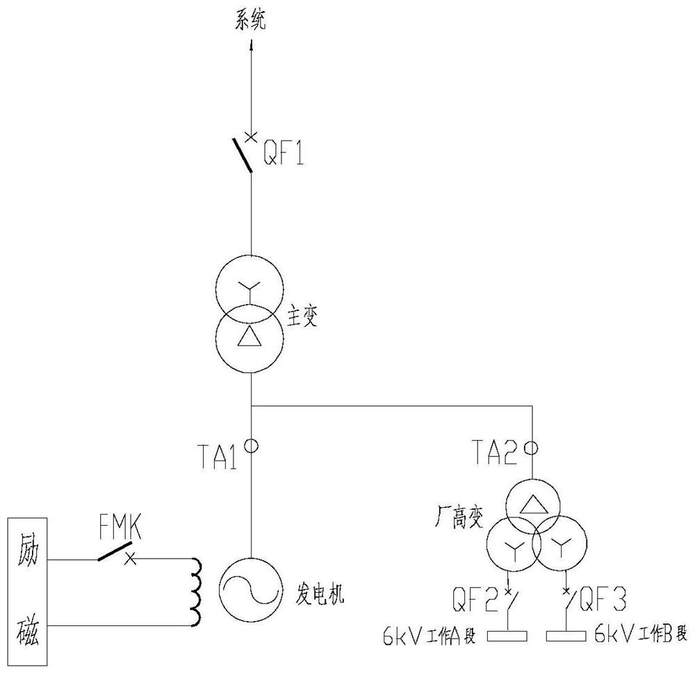
Many cases have shown that when the generator-transformer unit of a power plant is boosted but not yet connected to the grid, if the main transformer, high power transformer and other transformers (attached figure 1 ) If the residual magnetism in the iron core is not eliminated, the transformer will generate a large excitation inrush current, which will cause the voltage and current waveform distortion at the generator outlet, and cause false alarms or even malfunctions of the relay protection device
At present, the relay protection and safety automatic devices of power plants are still unable to distinguish this abnormal phenomenon
It is necessary to untie the main equipment on site and carry out investigations one by one by section. It takes a lot of inspection and test time to make an accurate judgment and the generator set can resume grid-connected operation, which often causes a large power loss and is harmful to the safe and economical operation of the power plant. Extremely unfavorable

Method used


Image

  • System and method for automatically judging residual magnetism of transformer of power plant
  • System and method for automatically judging residual magnetism of transformer of power plant
  • System and method for automatically judging residual magnetism of transformer of power plant

Examples


Embodiment Construction

[0021] In order to make those skilled in the art better understand the solutions of the present invention, the technical solutions in the embodiments of the present invention will be clearly and completely described below with reference to the accompanying drawings in the embodiments of the present invention. Obviously, the described embodiments are only The embodiments are part of the present invention, not all of the embodiments, and are not intended to limit the scope of the present disclosure. Also, in the following description, descriptions of well-known structures and techniques are omitted to avoid unnecessarily obscuring the concepts disclosed in the present invention. Based on the embodiments of the present invention, all other embodiments obtained by persons of ordinary skill in the art without creative efforts shall fall within the protection scope of the present invention.

[0022] The accompanying drawings show a schematic structural diagram of an embodiment accor...


PUM


Abstract

The invention discloses a power plant transformer residual magnetism automatic discrimination system and method. The system comprises an excitation system, a magnetic field circuit breaker FMK, an excitation coil, a generator, a first current transformer, a second current transformer, a high plant transformer, a main transformer, a grid-connected circuit breaker, a first circuit breaker, a 6kV working A section, a second circuit breaker, a 6kV working B section and a generator-transformer group protection device. The excitation system is connected with the excitation coil through the magnetic field circuit breaker, the excitation coil is coupled with the generator, the output end of the generator is divided into two paths after passing through the first current transformer, one path is connected with the high-voltage side of the high-voltage transformer through the second current transformer, and the other path is connected with the system through the main transformer and the grid-connected circuit breaker. The low-voltage side of the high-voltage plant transformer is divided into two paths, one path is connected with the 6kV working section A through the first circuit breaker, the other path is connected with the 6kV working section B through the second circuit breaker, and the system and the method can automatically identify whether residual magnetism influencing starting of a unit exists in the transformer or not.

Description

technical field [0001] The invention belongs to the technical field of electrical equipment of power plants, and relates to an automatic determination system and method for remanence of transformers in power plants. Background technique [0002] The transformer is an important equipment in the power grid. The stable operation of the transformer plays a key role in ensuring the continuous and reliable power supply of the power system. Due to the inherent hysteresis of ferromagnetic materials, residual magnetism remains in the transformer core. The power transformer will generate residual magnetism after the DC test. The amount of residual magnetism depends on the DC current intensity and time passed by the transformer winding. The longer the time, the greater the residual magnetism. Many cases have shown that when the generator-transformer group of the power plant is boosted but not connected to the grid, if the main transformer, high-power transformer and other transformers...

Claims


Application Information

Patent Timeline
Patent Type & Authority Applications(China)
IPC IPC(8): G01R33/12G01R33/02
CPCG01R33/12G01R33/02
Inventor 李泽财都劲松曹浩军付东岩刘瞻张宇博周亚群高沛荣任民侯中峰
Owner XIAN THERMAL POWER RES INST CO LTD
Learn More