Temperature and humidity monitoring device for atmospheric environment

A monitoring device and atmospheric environment technology, applied to measuring devices, cleaning methods using tools, using multiple variables to indicate weather conditions, etc., can solve problems such as poor monitoring and broadcast accuracy, inconvenient monitoring, and affecting the measurement accuracy of testing instruments , to achieve the effect of ensuring stability and good adaptability

Pending Publication Date: 2022-07-29
张明
View PDF0 Cites 0 Cited by
  • Summary
  • Abstract
  • Description
  • Claims
  • Application Information

AI Technical Summary

Problems solved by technology

[0002] In the weather forecast, there are often broadcasts of temperature and humidity in the atmospheric environment. The monitoring of temperature and humidity in urban areas is mainly carried out through the monitoring equipment in the weather station, while the monitoring of temperature and humidity in mountainous areas and areas covered by shrubs is mostly carried out through the surrounding Moderate environment and temperature prediction In mountainous areas, the accuracy of monitoring and broadcasting is poor. Due to the large number of trees, the humidity in mountainous areas is often higher than that of the peripheral areas, and the temperature is often lower than that of the peripheral areas. Therefore, in the case of demand, it is necessary to Carry out environmental monitoring in trees in mountainous areas, but the base station equipment in the prior art is difficult to deploy in the forest, which brings inconvenience to the monitoring. Secondly, due to the special environment in the trees, there are many fallen leaves on the branches, which affects the measurement accuracy of the detection instrument, so , we propose a temperature and humidity monitoring device for atmospheric environments

Method used


Image

  • Temperature and humidity monitoring device for atmospheric environment
  • Temperature and humidity monitoring device for atmospheric environment
  • Temperature and humidity monitoring device for atmospheric environment

Examples


Embodiment Construction

[0029] The following description serves to disclose the invention to enable those skilled in the art to practice the invention. The preferred embodiments described below are given by way of example only, and other obvious modifications will occur to those skilled in the art.

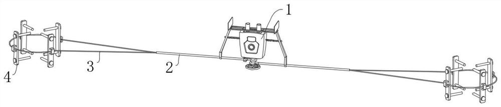
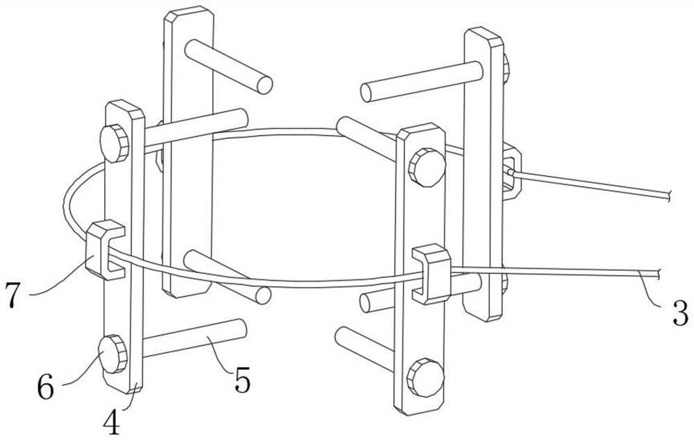
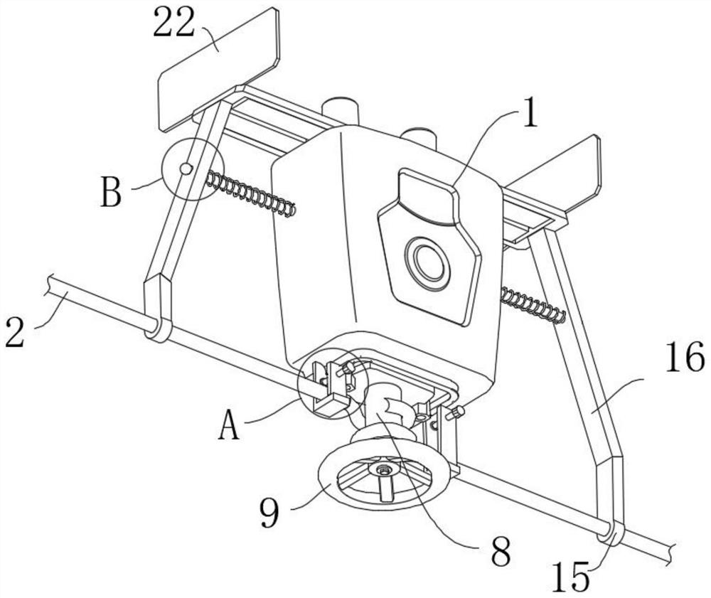
[0030] like Figure 1-Figure 9 A temperature and humidity monitoring device for an atmospheric environment is shown, including a detector main body 1, a detection head 23 is arranged on the upper end surface of the detector main body 1, a winding mechanism is arranged on the lower end surface of the detector main body 1, and the winding mechanism The main rope 2 extending in the direction of both sides is wound. The lower end surface of the detector main body 1 is provided with a clamping mechanism for clamping the main rope 2 near both sides. The end of the main rope 2 away from the detector main body 1 is fixedly connected with a The branch rope 3, the outer side of the branch rope 3 is provided with ...


PUM


Abstract

The invention relates to the technical field of temperature and humidity monitoring, in particular to a temperature and humidity monitoring device for an atmospheric environment, which comprises a detector main body, a detection head is arranged on the upper end surface of the detector main body, a winding mechanism is arranged on the lower end surface of the detector main body, and a main rope extending towards two sides is wound on the winding mechanism. Clamping mechanisms for clamping a main rope are arranged at the positions, close to the two sides, of the lower end face of the detector body, a branch rope is fixedly connected to the end, away from the detector body, of the main rope, and the outer side of the branch rope is movably sleeved with a plurality of mounting plates. In the arrangement process, the device can be arranged at a proper height position according to needs, can be flexibly adapted to trunks with different thicknesses for use, is good in adaptability, has a self-maintenance function, and does not affect the detection precision due to the fact that too many sundries are accumulated at the detection head after long-time use.

Description

technical field [0001] The invention relates to the technical field of temperature and humidity monitoring, in particular to a temperature and humidity monitoring device used in atmospheric environment. Background technique [0002] In the weather forecast, there is often a broadcast of the temperature and humidity in the atmospheric environment. The monitoring of the temperature and humidity in urban areas is mainly carried out by the monitoring equipment in the weather station, while the temperature and humidity monitoring in the mountainous areas and shrub forest-covered areas is mostly carried out through the surrounding area. The environment is moderate and the temperature is forecasted in the mountainous area, and the monitoring and broadcasting accuracy is poor. Due to the large number of trees, the humidity in the mountainous area is often higher than that of the peripheral area, and the temperature is often lower than the peripheral area. Therefore, in the case of de...

Claims


Application Information

Patent Timeline
IPC IPC(8): G01W1/02G01D21/02B08B1/00B08B13/00
CPCG01W1/02G01D21/02B08B13/00B08B1/12Y02A50/20
Inventor 张明
Owner 张明
Why Eureka
Try Eureka