Crawling type high-voltage cable state monitoring device

A state monitoring device and high-voltage cable technology, which is applied in the direction of measuring devices, measuring electricity, and measuring electrical variables, can solve problems such as the adverse effects of dynamic capacity increase and the difficulty of obtaining the local state of wires, so as to prevent the local state from being poor or the wires from being damaged. Loss, improve adaptability, improve the effect of conveying capacity

Pending Publication Date: 2022-07-29
武汉中谷迈拓科技有限责任公司
View PDF0 Cites 0 Cited by
  • Summary
  • Abstract
  • Description
  • Claims
  • Application Information

AI Technical Summary

Problems solved by technology

[0002] Dynamic capacity increase technology refers to the installation of online detection devices on the transmission line to monitor the status of the conductors (conductor temperature, tension, sag, etc.) and environmental conditions (ambient temperature, sunshine and wind speed, etc.). Under the premise, the maximum allowable current carrying capacity of the conductor is calculated according to the Morgan et al. current carrying capacity model, and the hidden capacity of the line is fully utilized to increase the actual transmission capacity of the transmission line. Distributed between the iron towers, the existing online detection devices are usually installed on the iron towers. When detecting the state of the wires, it is difficult to obtain the local state of the wires. For example, the sag of the wires is easily affected by the clarity of the captured image. If there are foreign objects or abnormal defects in the high-voltage wires, the effect of dynamic capacity increase will be adversely affected. Under the premise of ensuring safety, the existing crawling high-voltage cable status monitoring device cannot solve the above problems , for this reason, the present invention proposes a crawling high-voltage cable condition monitoring device

Method used


Image

  • Crawling type high-voltage cable state monitoring device
  • Crawling type high-voltage cable state monitoring device
  • Crawling type high-voltage cable state monitoring device

Examples


Embodiment approach

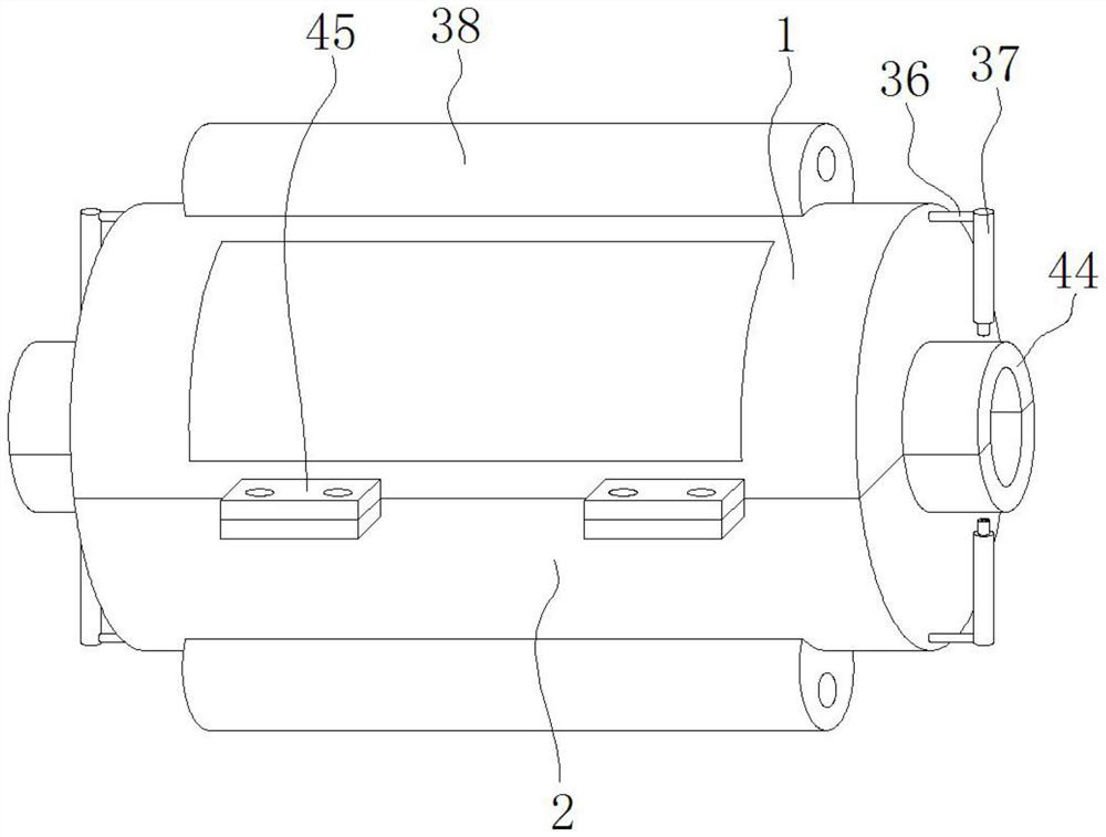
[0028] As a preferred embodiment of the present invention, one side of the upper half-shell 1 and the lower half-shell 2 is fixedly installed with a constricted half-pipe 44 .

[0029] As a preferred embodiment of the present invention, the upper half shell 1 and the lower half shell 2 are fixedly mounted with connecting seats 45 , and the connecting seats 45 on the upper half shell 1 and the lower half shell 2 are connected by bolts.

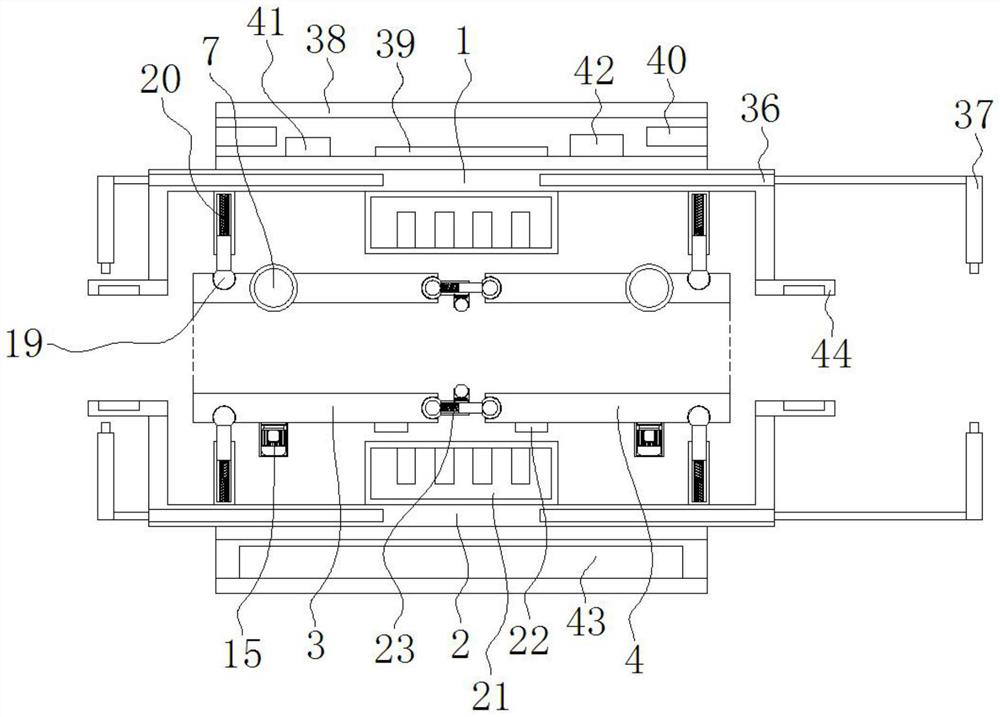
[0030] As a preferred embodiment of the present invention, the electromagnetic induction power taking device 21 is respectively connected with the processor 39, the inclination sensor 22, the crawling motor 15, the electric push rod 36, the micro laser 37, the camera 40, the wireless transceiver 41, the speed The sensor 42 and the monitoring sensor group 43 are electrically connected, and the processor 39 is respectively connected with the inclination sensor 22, the crawling motor 15, the electric push rod 36, the micro laser 37, the camera 40, ...


PUM


Abstract

A crawling type high-voltage cable state monitoring device provided by the present invention comprises a processor, an upper half shell, a lower half shell, a left attaching crawling pipe and a right attaching crawling pipe, the left attaching crawling pipe and the right attaching crawling pipe each comprise an upper half pipe and a lower half pipe, and a plurality of rubber crawling wheels are movably embedded in the outer side of each of the upper half pipes and the lower half pipes. The creeping type high-voltage cable state monitoring device is reasonable in design, the left attaching creeping pipe and the right attaching creeping pipe are matched to enable the whole creeping type high-voltage cable state monitoring device to be attached to a high-voltage cable to creeping bidirectionally, on one hand, the state and environmental conditions of local parts of the high-voltage cable can be monitored in real time, and the whole wire can be patrolled and monitored; therefore, a more accurate state value of the high-voltage line is obtained, so that the actual maximum allowable current-carrying capacity of the lead is obtained, the actual transmission capacity of the power transmission line is improved on the premise of ensuring safety, and danger caused by poor local state or lead damage is prevented.

Description

technical field [0001] The invention belongs to the technical field of electric power equipment, and particularly relates to a crawling type high-voltage cable state monitoring device. Background technique [0002] Dynamic capacity expansion technology refers to the installation of online detection devices on transmission lines to monitor the conductor status (conductor temperature, tension, sag, etc.) and environmental conditions (ambient temperature, sunshine and wind speed, etc.) Under the premise, the maximum allowable current carrying capacity of the wire is calculated according to the Morgan equal current carrying capacity model, making full use of the implicit capacity of the line, and improving the actual transmission capacity of the transmission line, which has strong practicability. The transmission lines are all sections. Distributed between each tower, the existing on-line detection device is usually installed on the tower, when the state of the wire is detected,...

Claims


Application Information

Patent Timeline
Patent Type & Authority Applications(China)
IPC IPC(8): G08B21/18G01R31/00G01B21/20
CPCG08B21/18G01R31/00G01B21/20
Inventor 雷传辉散威郑涛李璇
Owner 武汉中谷迈拓科技有限责任公司
Why Eureka
Try Eureka