Simulation fault motion matching type box body structure and seismic fault simulation experiment platform

A box structure and motion technology, applied in the testing of machines/structural components, teaching models, instruments, etc., can solve the problems of waste, inability to realize tailoring, time-consuming and labor-intensive, and achieve the effect of flexible construction and disassembly

Active Publication Date: 2022-07-29
JIANGHAN UNIVERSITY
View PDF10 Cites 2 Cited by
  • Summary
  • Abstract
  • Description
  • Claims
  • Application Information

AI Technical Summary

Problems solved by technology

[0005] However, the size of the above-mentioned box structure is fixed. When carrying out cross-fault simulation experiments of model structures of different scales, it is still impossible to achieve tailor-made clothing, which brings time-consuming, labor-intensive and unnecessary waste problems.

Method used


Image

  • Simulation fault motion matching type box body structure and seismic fault simulation experiment platform
  • Simulation fault motion matching type box body structure and seismic fault simulation experiment platform
  • Simulation fault motion matching type box body structure and seismic fault simulation experiment platform

Examples


Embodiment 1

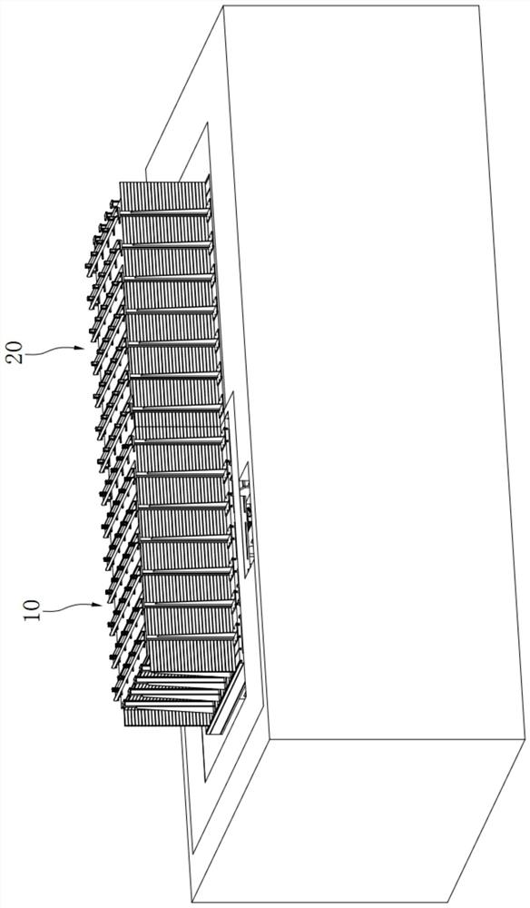
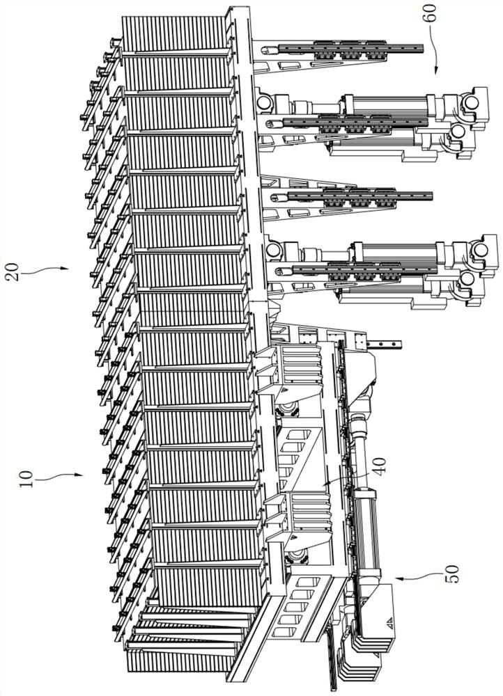
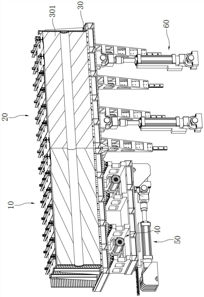
[0060] like Figure 1 to Figure 3 As shown, it is the first preferred embodiment of the seismic fault simulation experimental platform of the present invention. The seismic fault simulation experiment platform includes a left box body 10 , a right box body 20 , a first driving mechanism 40 , a second driving mechanism 50 and a third driving mechanism 60 .

[0061] Wherein, the right side of the left box 10 has an opening, and the left side of the right box 20 has an opening. After the left and right are arranged in a coordinated manner, the left box 10 and the right box 20 form a matching box structure, and the inner cavities of the two are connected. A accommodating cavity 30 for accommodating the soil layer 301 is formed.

[0062] Specifically, as figure 2 As shown, the left box body 10 and the right box body 20 both include a main box body 1 , an end cover 2 and a pressurizing device 4 . The main box 1 has openings on both sides along the left and right directions, and ...

Embodiment 2

[0070] like Figures 4 to 11 As shown, it is the second preferred embodiment of the seismic fault simulation experimental platform of the present invention. The difference from Example 1 is:

[0071] In this embodiment, as Figure 4 and Figure 5 As shown, an adjustable box 3 is installed on the other side of the main box 1, and the side edge of the adjustable box 3 facing the side of the main box 1 is detachably connected with the side edge of the other side of the main box 1, The side edge of the adjustable box body 3 facing away from the main box body 1 is bent outward to form a second convex edge 31. The second convex edge 31 of the adjustable box body 3 on the left box body 10 can be opposite to the right box body. The second convex edge 31 of the adjustable box body 3 on the body 20 moves and is always in close contact with the second convex edge 31 of the adjustable box body 3 on the right box body 20 .

[0072] Denote the angle between the contact surface and the h...


PUM


Abstract

The invention relates to the technical field of research and development of seismic fault motion simulation test instruments, in particular to a fault motion simulation matching type box body structure and a seismic fault simulation test platform. The fault motion simulation matching type box body structure comprises a left box body and a right box body which are arranged in a left-right matching mode, and an inner cavity of the left box body and an inner cavity of the right box body are communicated and form a containing cavity for containing a soil layer; each of the left box body and the right box body comprises a main box body, openings are formed in the two sides in the left-right direction, and an opening is formed in the top side; and an end cover. According to the device, the at least two transverse battens which are sequentially arranged in the vertical direction form the plugging component, and the plugging component is assembled between the two adjacent vertical supporting frames which are arranged at intervals in the left-right direction, so that the main box body with proper length and height can be formed by selecting a proper number of transverse battens and a proper number of vertical supporting frames; and the research requirements of to-be-tested models with different sizes are met.

Description

technical field [0001] The invention relates to the technical field of research and development of seismic fault motion simulation test instruments, in particular to a box body structure that simulates fault motion and a seismic fault simulation experiment platform. Background technique [0002] With the needs of human social and economic development, the construction of large-scale civil engineering, transportation, water conservancy, marine and other infrastructure projects has become more and more common. Infrastructure is under threat from seismic fault activity. When tunnels, bridges, railways, pipelines, buildings and other large engineering facilities pass through / cross the active fault zone, the movement of the fault will cause tension, extrusion or shearing of the engineering structure, resulting in large deformation of the structure and facilities until they are destroyed. Once it happens, its social and economic losses will be incalculable. [0003] At present, ...

Claims


Application Information

Patent Timeline
Patent Type & Authority Applications(China)
IPC IPC(8): G09B23/40G01M99/00
CPCG09B23/40G01M99/00
Inventor 徐龙军杨绪剑
Owner JIANGHAN UNIVERSITY
Why Eureka
Try Eureka