
Rock seepage characteristic testing device and method under coupling of thermal shock and dynamic shock

A dynamic shock and characteristic testing technology, which is used in measurement devices, permeability/surface area analysis, suspension and porous material analysis, etc. Problems such as geological conditions and working conditions

Inactive Publication Date: 2020-11-20
CENT SOUTH UNIV
View PDF10 Cites 2 Cited by
  • Summary
  • Abstract
  • Description
  • Claims
  • Application Information

AI Technical Summary

Problems solved by technology

[0004] However, the existing test equipment cannot meet the above multi-field coupling and dynamic disturbance direction coupling conditions.
Part of the test equipment, for example, the method for measuring the thermal shock factor in the rock thermal shock fracture process disclosed in the patent CN109709135A, can only realize the thermal shock effect of the rock under the condition of heating in a water bath, but cannot be close to the in-situ geological conditions and engineering conditions suffered by the rock. conditions, and further testing of process changes in rock properties

Method used


Image

  • Rock seepage characteristic testing device and method under coupling of thermal shock and dynamic shock
  • Rock seepage characteristic testing device and method under coupling of thermal shock and dynamic shock
  • Rock seepage characteristic testing device and method under coupling of thermal shock and dynamic shock

Examples


Embodiment Construction

[0045] The following will clearly and completely describe the technical solutions in the embodiments of the present invention in conjunction with the accompanying drawings in the embodiments of the present invention. Obviously, the described embodiments are only some of the embodiments of the present invention, not all of them. Based on the embodiments of the present invention, all other embodiments obtained by persons of ordinary skill in the art without making creative efforts belong to the protection scope of the present invention.

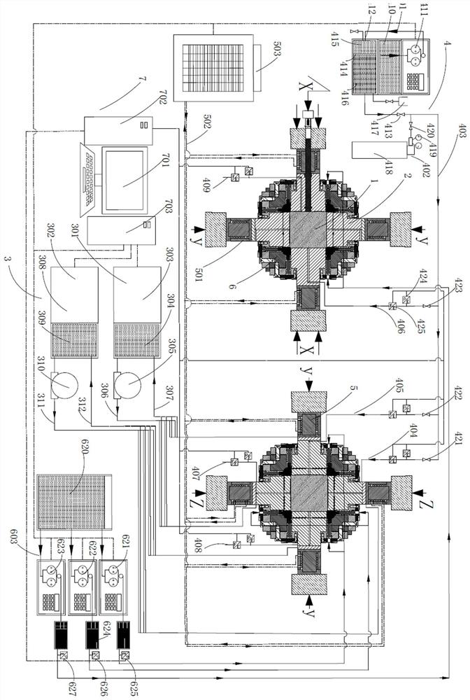
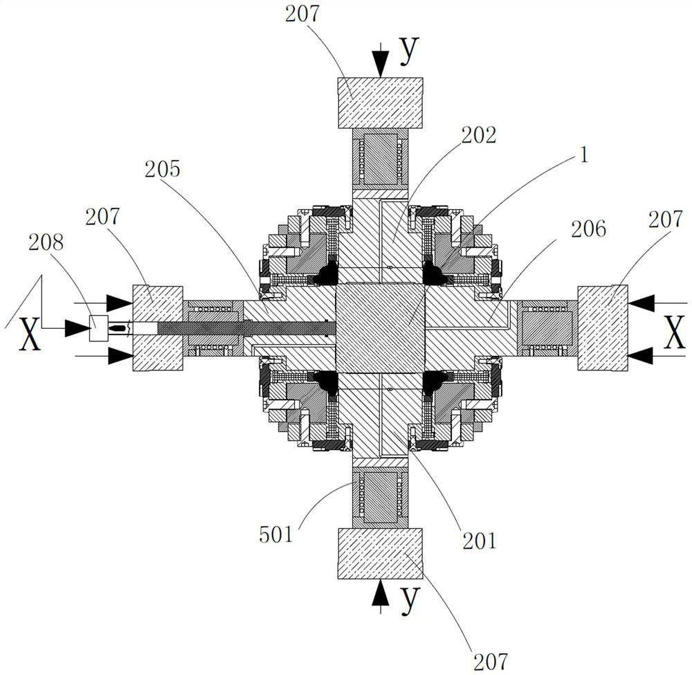
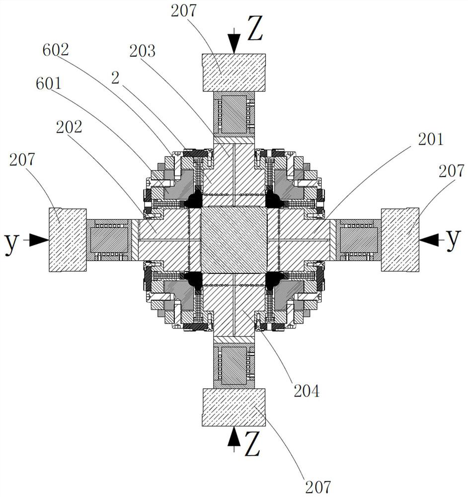
[0046] see figure 1, a test device for rock seepage characteristics under the coupling of thermal shock and dynamic shock, comprising a true triaxial stress loading system 2 for applying a true triaxial load to a rock test piece 1, a thermal shock load system 2 for applying a thermal shock load to the rock test piece 1 The generating mechanism 3, the true triaxial boundary seepage sealing mechanism 6 and the control and monitoring mechanism 7 s...


PUM


Abstract

The invention discloses a rock seepage characteristic testing device and method under coupling of thermal shock and dynamic shock. The testing device comprises a true triaxial stress loading system and a thermal shock generating mechanism; criss-cross infiltration guide grooves are cut in the loading end faces of an upper loading head, a rear loading head and a right loading head of the true triaxial stress loading system, and liquid inlet flow channels communicated with the infiltration guide grooves are formed in the upper loading head, the rear loading head and the right loading head; criss-cross liquid collection guide grooves are cut in the loading end faces of the lower loading head, the front loading head and the left loading head, and liquid return flow channels communicated with the liquid collection guide grooves are formed in the upper loading head, the rear loading head and the right loading head; a through hole is formed in the center of the left loading head; and a disturbance incident rod for applying impact load to a rock test piece is arranged in the through hole in a sliding mode. The rock in-situ high ground stress, high ground temperature, high osmotic pressure,high temperature difference and dynamic load action environment can be simulated, and rock seepage characteristics in a multi-field coupling environment can be analyzed and researched.

Description

technical field [0001] The invention belongs to the technical field of deep rock testing, in particular to a device and method for testing rock seepage characteristics under thermal shock and dynamic shock coupling. Background technique [0002] In recent years, with the rapid development of geotechnical engineering construction in my country, the problems of geotechnical engineering have become increasingly complex. However, bridges and tunnels account for more than 80% of the entire Sichuan-Tibet Railway, reaching 1200km. Engineering construction is facing unprecedented engineering geological challenges, facing special geological conditions such as high cold, high ground stress, high water pressure, and high ground temperature. Under the action of high ground stress, high ground temperature, high seepage pressure, high temperature difference and multi-field coupling of dynamic load, the catastrophe process and mechanism of rock and soil mass show particularity and complexi...

Claims


Application Information

Patent Timeline
Patent Type & Authority Applications(China)
IPC IPC(8): G01N15/08
CPCG01N15/0806G01N15/0826
Inventor 李夕兵陈江湛尹土兵
Owner CENT SOUTH UNIV
Learn More