Main and standby power supply switching circuit and electronic equipment

A technology for switching circuits, main and backup power supplies, applied in the field of power supplies, can solve problems such as increasing layout space and product cost, and achieve the effect of solving unstable work

Pending Publication Date: 2022-07-29
高新兴物联科技股份有限公司
View PDF0 Cites 0 Cited by
  • Summary
  • Abstract
  • Description
  • Claims
  • Application Information

AI Technical Summary

Problems solved by technology

Although the current industry has a corresponding solution to the problem of power switching, such as increasing the load capacitance to compensate for the voltage drop during the power switching process, this method does not solve the problem in essence, and increases the load capacitance while increasing Layout space and product cost

Method used


Image

  • Main and standby power supply switching circuit and electronic equipment
  • Main and standby power supply switching circuit and electronic equipment
  • Main and standby power supply switching circuit and electronic equipment

Examples


Embodiment 1

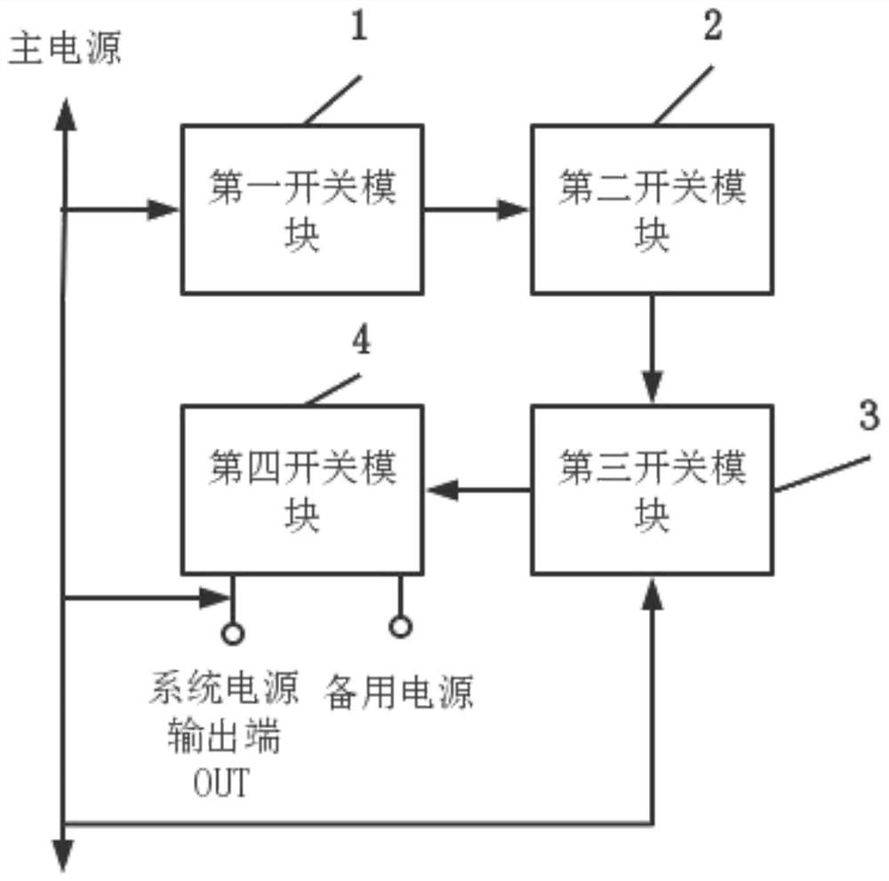
[0035] In order to solve the technical problem of increasing the layout space and product cost caused by increasing the load capacitance to compensate for the voltage drop during the power switching process of electronic equipment, this embodiment provides a main and standby power switching circuit, please refer to figure 1 , figure 1 It is a schematic diagram of an implementation of the main and standby power supply switching circuit provided by the embodiment of the present invention. The main and backup power switching circuit includes a first switch module 1 to a fourth switch module 4 connected in sequence;

[0036]The control terminal of the first switch module 1 is connected to the main power supply, and is used to control the second switch module 2 to be disconnected when the main power supply is in place, and to control the second switch module 2 to be turned on when the main power supply is not in place. ;

[0037] The second switch module 2 is used to cooperate wi...

Embodiment 2

[0057] This embodiment provides an electronic device, the electronic device includes the main-standby power supply switching circuit of the above-mentioned first embodiment. The electronic device of this embodiment can switch to the standby power supply at the moment when the main power supply stops supplying power, and after the preset delay time when the main power supply starts to supply power, that is, after the main power supply starts to supply power steadily, the standby power supply is stopped, thereby completely solving the problem. The problem of unstable operation of electronic equipment caused by power switching, and compared with the scheme of increasing the load capacitance, it not only saves the layout space but also reduces the product cost. Further, the main and standby power supply switching scheme is completely realized by hardware circuit, and the working reliability is high. The specific structure of the main and standby power supply switching circuits is ...


PUM


Abstract

The invention discloses a main and standby power supply switching circuit and electronic equipment, and belongs to the technical field of power supplies. The main and standby power supply switching circuit comprises a first switch module, a second switch module, a third switch module and a fourth switch module, the control end of the first switch module is connected with a main power supply, the input end of the fourth switch module is connected with a standby power supply, the output end of the fourth switch module is connected with the output ends of the main power supply and a system power supply, and the control end of the fourth switch module is connected with the third switch module. By adopting the main and standby power supply switching circuit provided by the embodiment of the invention, under the control of the main power supply, through mutual cooperation of the four switch modules, power supply of the standby power supply is realized at the moment when the main power supply stops power supply, and power supply of the standby power supply is stopped after preset delay when the main power supply starts power supply; therefore, the problem of unstable work of electronic equipment caused by power supply switching can be thoroughly solved, and compared with a scheme of increasing load capacitance, the main and standby power supply switching circuit not only saves layout space, but also reduces product cost.

Description

technical field [0001] The invention relates to the technical field of power supplies, in particular to a main and backup power supply switching circuit and electronic equipment. Background technique [0002] At present, many electronic devices support two power supply modes, the main power supply and the backup power supply. For example, products such as OBD (On-Board Diagnostics, vehicle-mounted automatic diagnostic system), Tracker (positioning tracker) and other products are such electronic devices. The advantage of this power supply mode is that when the main power supply is not in place, the electronic device can still be powered by the backup power supply and work normally, and because the main power supply is supported, the requirement for the capacity of the backup power supply is reduced. [0003] However, since two power modes are supported, there are switching scenarios of two power sources for this type of electronic device, and it is necessary to ensure that t...

Claims


Application Information

Patent Timeline
Patent Type & Authority Applications(China)
IPC IPC(8): H02J9/06
CPCH02J9/06
Inventor 陈俊杨飞
Owner 高新兴物联科技股份有限公司
Why Eureka
Try Eureka