
Multifunctional optical fiber converter

An optical fiber converter and multi-functional technology, which is applied in optical fiber transmission, selection device of multiplexing system, electrical components, etc., can solve problems such as inability to access optical fiber, achieve convenient use, high reliability, and improve work efficiency Effect

Pending Publication Date: 2022-07-29
STATE GRID HEBEI ELECTRIC POWER CO LTD +1
View PDF2 Cites 0 Cited by
  • Summary
  • Abstract
  • Description
  • Claims
  • Application Information

AI Technical Summary

Problems solved by technology

The substrate layer (3) has an area extending beyond the piezoelectric layer (6), and the coupling device is installed in the extended area (7); the patent cannot access optical fibers, no improvement is required

Method used


Image

  • Multifunctional optical fiber converter
  • Multifunctional optical fiber converter
  • Multifunctional optical fiber converter

Examples


Embodiment 1

[0049] like Figure 1-4 shown:

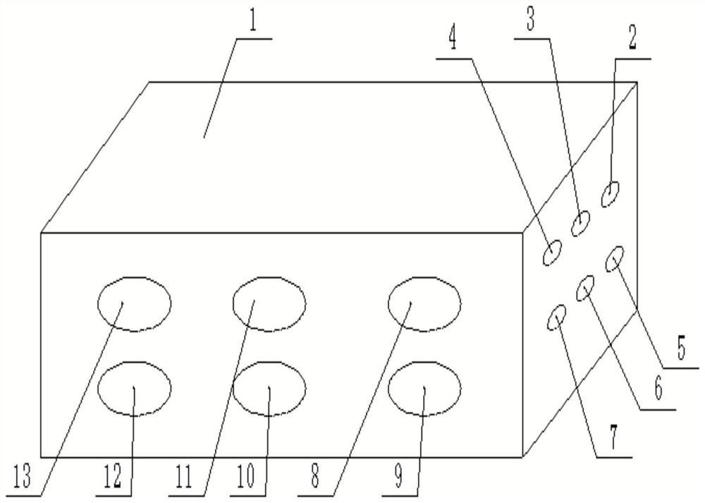
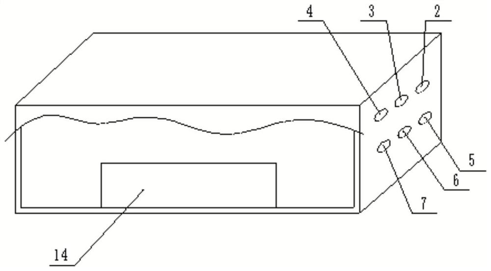
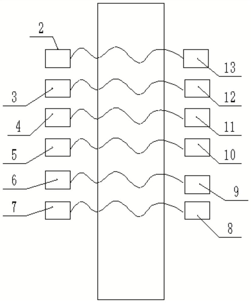
[0050] The multifunctional optical fiber converter includes a casing 1; also includes a coupler 14 arranged in the casing 1 and a conversion joint arranged on the casing 1; the conversion joint is electrically connected to the coupler 14 .

[0051] The conversion connector includes six ST interface jacks provided on the side of the housing 1 .

[0052] The six ST interface jacks are the first ST interface jack 2, the second ST interface jack 3, the third ST interface jack 4, the fourth ST interface jack 5, the fifth ST interface jack 6 and The sixth ST interface jack 7.

[0053] The six ST interface jacks are divided into two rows, one of which is arranged with the first ST interface jack 2, the second ST interface jack 3 and the third ST interface jack 4, and the other row is arranged with the fourth ST interface jack. Hole 5 , fifth ST interface jack 6 and sixth ST interface jack 7 .

[0054] The adapter also includes six sockets on the fr...

Embodiment 2

[0065] The structure of this embodiment is basically the same as that of Embodiment 1,

[0066] This embodiment differs from Embodiment 1 in that:

[0067] The material of the shell 1 is degradable plastic;

[0068] The use of degradable plastics is environmentally friendly; degradable plastics refer to a class of products whose properties can meet the requirements of use, remain unchanged during the storage period, and can be degraded into environmentally harmless substances under natural conditions after use. plastic.

[0069] The working principle of this embodiment is basically the same as that of Embodiment 1 and will not be repeated here.

Embodiment 3

[0071] The structure of this embodiment is basically the same as that of Embodiment 1,

[0072] The difference is that the shell 1 is made of nylon material; nylon material has the characteristics of high strength and is not afraid of pressure, and is also a good choice. The disadvantage is that it is easy to cause environmental pollution and cannot be reused.

[0073] The working principle of this embodiment is basically the same as that of Embodiment 1 and will not be repeated here.


PUM


Abstract

The invention relates to a multifunctional optical fiber converter which comprises a shell. The coupler is arranged in the shell; the conversion joint is arranged on the shell; the adapter is electrically connected with the coupler; the conversion joint comprises six ST interface jacks arranged on the side surface of the shell; the six ST interface jacks are respectively a first ST interface jack, a second ST interface jack, a third ST interface jack, a fourth ST interface jack, a fifth ST interface jack and a sixth ST interface jack; the adapter further comprises six jacks arranged on the front surface of the shell, wherein two jacks are round FC jacks with threads, two clamping type square SC jacks and two clamping type small square LC jacks; the multi-purpose optical fiber converter has the beneficial effects that the multi-purpose optical fiber converter is suitable for searching GOOSESV (Generic Object Oriented SESV) broken link defects in an intelligent substation, verifying a protection device, verifying and checking an intelligent terminal and a merging unit and applying to other intelligent equipment.

Description

technical field [0001] The invention relates to the technical field of conversion joints, in particular to a multifunctional optical fiber converter. Background technique [0002] The traditional optical fiber connector is to connect two optical fiber plugs of the same type to realize the transmission of optical signals. However, with the increase of smart substations, the types of optical fiber plugs of various protection and automation devices are inconsistent. During maintenance, debugging and maintenance, jumpers of various types of plugs must be prepared in order to connect the debugging instrument to the equipment being debugged. If the plug type of the fiber jumper brought to the site is wrong, the work will not be carried out, which will seriously affect the work efficiency. [0003] At present, the adapters between optical fibers are connected through their internal open sleeves to ensure the connection performance between the optical fiber connectors, and various ...

Claims


Application Information

Patent Timeline
IPC IPC(8): H04Q1/02H04Q11/00H04B10/25
CPCH04Q1/028H04Q11/0003H04Q11/0071H04B10/25H04Q2201/804H04Q2201/04
Inventor 郑凯康娜娜白红勇张振星纪志辉黄石成张丹牛运腾尹世豪杨艳敏秦晓静王宏娟王巍刘保安韩楠王彦红贺鹏张涛王佳琪
Owner STATE GRID HEBEI ELECTRIC POWER CO LTD
Learn More